Display System Utilization
en-938821/2 4 - 29
4
4.6.5 Selection of Graphic Display Parameters and Part Contour Trace in Mixed
Machine Mode (MX)
Milling machines on which turning functions are added to the standard milling functions are called "mixed" machines.
This combination involves special features as regards graphic display parameter selection and part contour trace.
This section supplements:
- Section 4.6.1 of this milling operator manual, and
- Section 4.6.1 of the turning operator manual.
See Section 4.17 of the Programming Manual for the special programming related to mixed machines.
4.6.5.1 Selection of Graphic Display Parameters
Requirements
"GRAPHIC - PROGRAMMING" menu displayed (see 4.6).
Actions
Select "GRAPHIC DISPLAY PARAMETERS" ☞
)
0
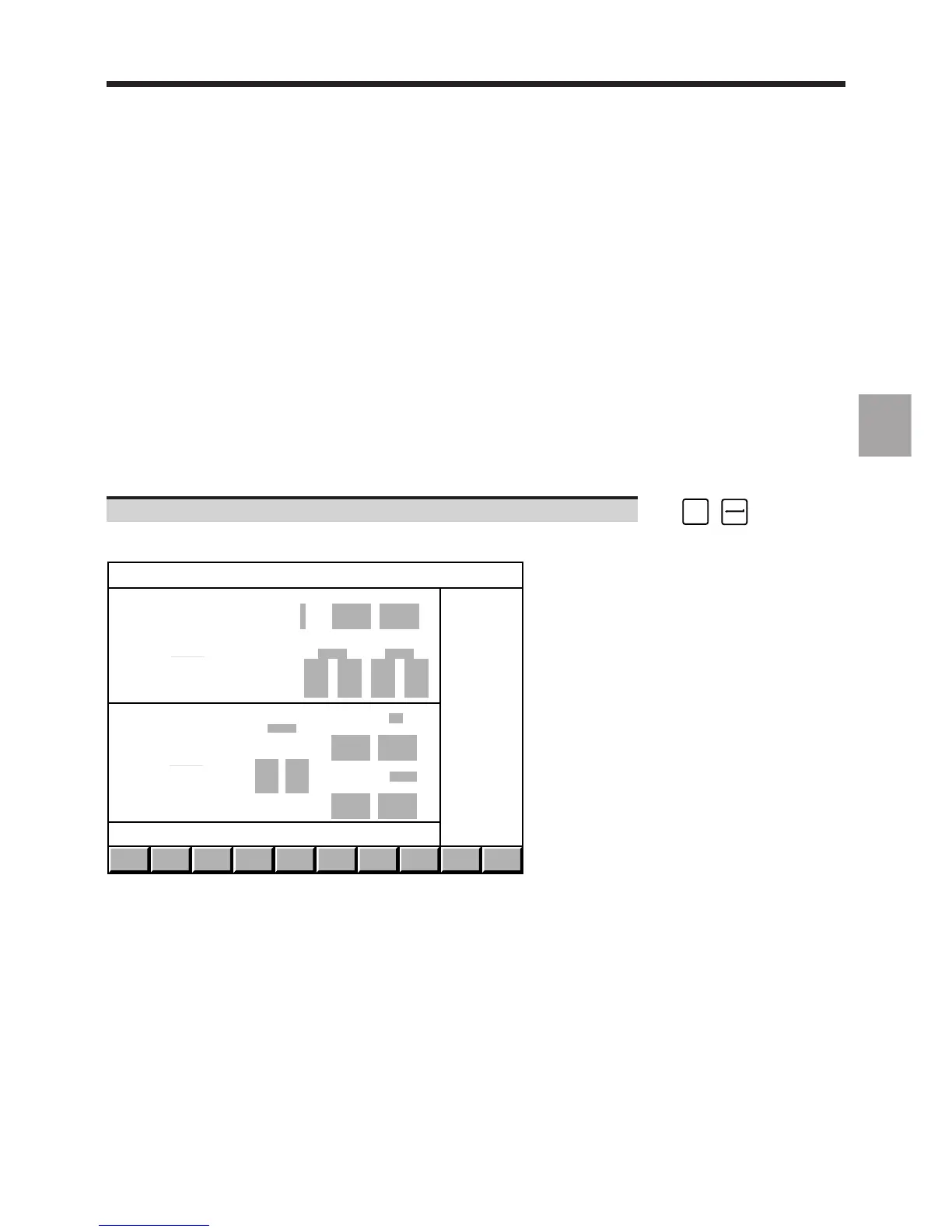
Display of the double window of the graphic display parameters page.
WINDOW
T/M
TRACE
TURN
TRACE
MILL
SCALE
T+ M
EXIT
-
-
-
-
-
-
-
-
-
-
-
-
-
-
-
-
-
-
-
TURN
MILL
AXIS Min Max
Horiz Z
Vert X
PLANE 1 PLANE 2
Program
Sequence
Program PLANE 1 X-Y
Min Max
Sequence
PLANE 2 from: BELOW
Min Max
Only the size of each of the two windows, "TURN" and "MILL", specific to mixed machines, is modified, but the windows
have the same organisation as the "GRAPHIC DISPLAY PARAMETERS" pages specific to lathes and milling
machines.
For the double window to be displayed, function 62, Mixed machine, must be enabled (see 2.3). Otherwise, the page
specific to milling machines is displayed.
The double window is incompatible with function 48, Boring function - processing of a radial axis.
Simulation by material removal is impossible on mixed machines.