Display
Jetson AGX Xavier Series Product DG-09840-001_v2.5 | 72
Parameter Requirement Units Notes
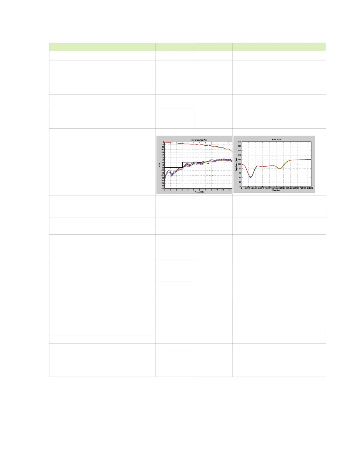
IL
resonance dip frequency
<= 1.7
<= 2
<= 3
< 6
> 12
dB @ 1GHz
dB @ 1.5GHz
dB @ 3GHz
dB @ 6GHz
GHz
TDR dip >= 85 Ω @ Tr=200ps
10%-90%. If TDR dip is 75~85ohm that dip
width should < 250ps
FEXT (PSFEXT) <= -50
<= -40
<= -40
dB at DC
dB at 3GHz
dB at 6GHz
PSNEXT is derived from an algebraic
summation of the individual NEXT effects on
each pair by the other pairs
Trace Impedance Diff pair 100 Ω
±10%. Target is 100Ω. 95Ω for the breakout
& main route is an implementation option.
Reference plane GND
Trace Length, Spacing and Skew
Trace loss characteristic: < 0.8
< 0.4
dB/in. @ 3GHz
dB/in. @ 1.5GHz
The max length is derived based on this
characteristic. The length constraint must
be re-defined if the loss characteristic is
changed.
Trace spacing (Pair-Pair) Stripline
Microstrip: pre 1.4b
Microstrip: 1.4b/2.0
3x
4x
5x to 7x
dielectric
For Stripline, this is 3x of the thinner of
above and below.
Trace spacing (Main Link to DDC)
Stripline
Microstrip
3x
5x
dielectric
For Stripline, this is 3x of the thinner of
above and below.
Max Total Delay (1.4b/2.0 - up to 5.94Gbps)
Stripline
Microstrip (5x spacing)
Microstrip (7x spacing)
63.5/2.5 (437)
50.8/2.0 (300)
63.5/2.5 (375)
mm/in (ps)
Propagation delay: 6.9ps/mm. for stripline,
5.9ps/mm. for microstrip).
Max Intra-Pair (within pair) Skew 0.15 (1) Mm (ps) See Notes 1, 2 and 3
Max Inter-Pair (pair to pair) Skew 150 ps See Notes 1, 2 and 3
Max
transition Via distance 1x Diff pair via pitch
For signals switching reference layers, add
one or two ground stitching vias. It is
recommended they be symmetrical to
signal vias.

 Loading...