connect audio output device, standard BNC interface
connect monitor, local video signal output
Alarm input and output.,RS485
and RS232
connect alarm input, alarm output device and PTZ
connect VGA display device, such as PC VGA display
connect USB device. Up-side link is USB2.0 which adapt to USB
storage device. Down-side link is USB1.1 which adapt to USB mouse.
audio output when connecting with DVR_WEB, this port will occupy
the signal from “A OUT”, only one of them can be took.
audio input when connecting with DVR_WEB, this port will occupy
the signal from “V OUT”, only one of them can be took.
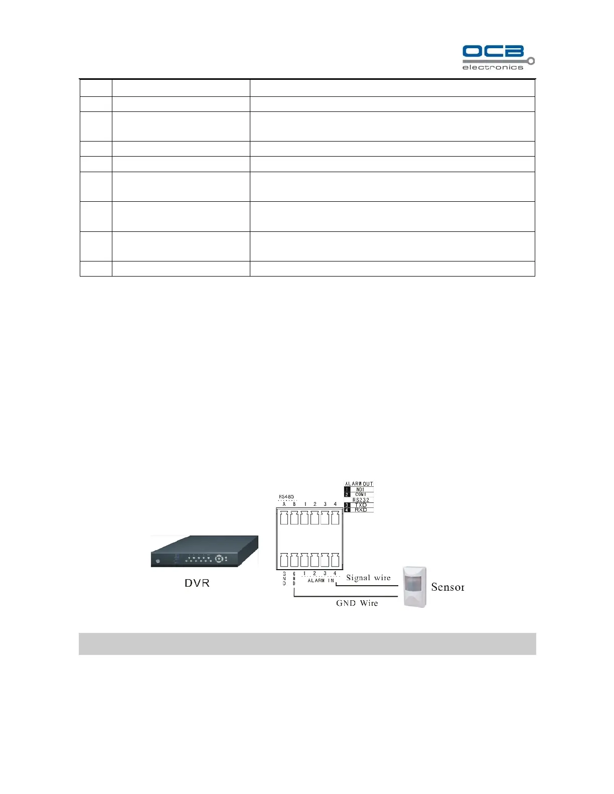
Section 4 External alarm in/out connection
Alarm in
The alarm input is NO/NC input, and this DVR has 4 ports for alarm input.
While sensor signal output is connected to DVR input, the signal port is connected to “1-4” port of ALARM IN,
GND port connect to GND port. Default alarm input mode is “NO”. So ALARM IN port connect to GND will be
considered as an alarm input; ALARM IN port disconnect with GND or has a high voltage (5V) input will be
considered as no alarm input by default;
Fig. 3
Note: external input voltage can not be higher than 5V.
Alarm out
Alarm output is NO/NC output, and this DVR has 1 port for alarm output.
When “NO1” and “COM1” was off, the alarm output disables, otherwise “NO1” and “COM1” was connected,