Section 6 Voice Communication
Fig. 6
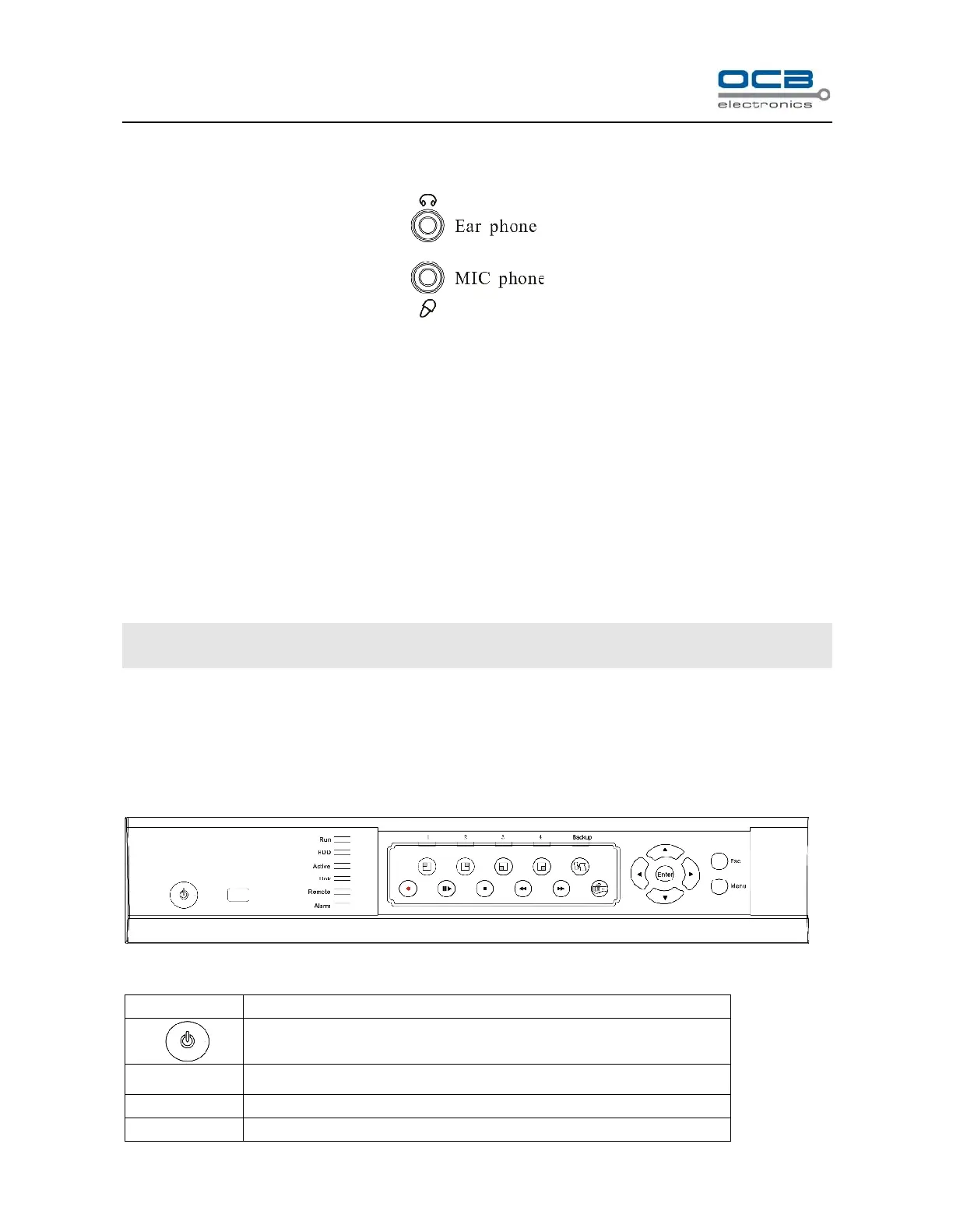
In the above illustration, the up icon is an ear phone socket and the down icon is a MIC phone socket. While
connect them with ear phone and MIC phone, a two-way communication can be realized when click the intercom
icon of the DVR_WEB software which has connected with the host. In the meantime, audio input from DVR can
be heard on PC; audio input from PC can be heard on audio output of DVR.
About the DVR_WEB setting please refer “Chapter Ⅶ”.
NOTE: Audio input of Voice Communication will take up the audio input of the first channel (A IN1). Audio
output of Voice Communication will take up the audio output (A OUT).
Chapter III DVR Operation
Section 1 DVR Front Panel
Fig. 7