64
ODB COMPANY
800-446-9823 LCT6000
Service Section
5.4 Impeller Installation and Removal, continued
Before removing the blower housing
face remove the negative battery cable to
ensure unit can not be started.
Fig. 1
Fig. 2
Fig. 3
Direct
Drive
Belt
Drive
Fig. 4
Fig. 5
INSTALLATION
1. Clean the shaft of any debris and remove any rust using a 120 grit
emory cloth.
2. Using an overhead crane or other suitable lifting device lift the impel-
ler on to the shaft. Turn the impeller to align the keyways of the shaft
with the keyway in the impeller.
3. Insert key into the keyway. A light sanding of the keyway may be
needed, as well as a few light blows with a rubber mallet.
4. Tap the bushing onto the shaft aligning the keyways.
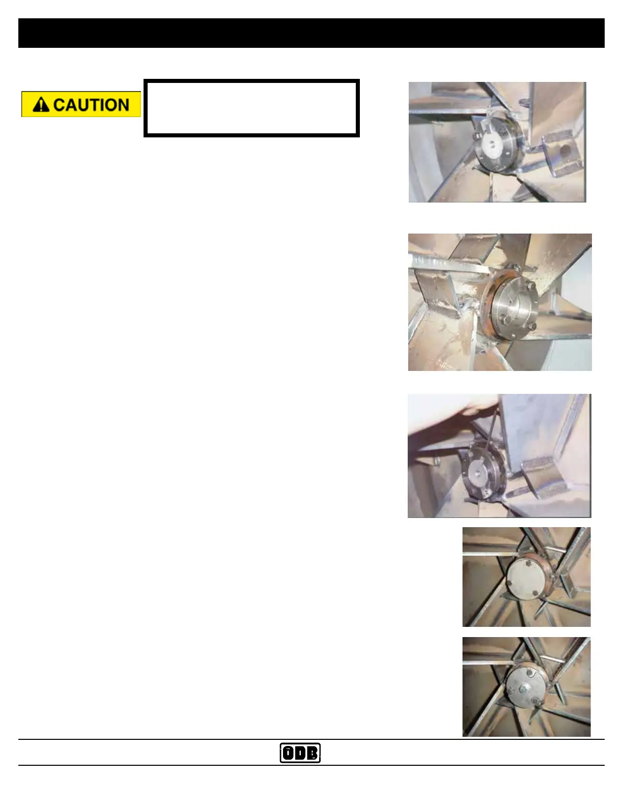
5. BELT DRIVE UNITS: Align the bushing and key to be ush with the
end of the shaft (Fig 1).
6. DIRECT DRIVE UNITS: The bushing and key should protrude from
the shaft about 1/2 inch (Fig. 2).
7. Put the 3 bolts into the non-threaded holes and drive them into the
impeller holes evenly. Alternate between the three bolts as you drive
the bolts in. Torque to 40 to 50 lbs/ft. There should be a gap of 3/8”
to 1/2” between the bushing and the impeller.
IMPORTANT: Slowly spin the impeller by hand making sure that the
back of the impeller is not hitting any of the bolt heads located at the
back of the blower housing.
8. If the bushing has a set screw on it, tighten the screw snug with an
allen wrench (Fig. 3). This will help keep the key in place.
9. Install the shaft protector on to the shaft (Fig. 4 or 5).