42049001TH Rev.1 63 /
Oki Data CONFIDENTIAL
3.4 Print Density Adjustment (Calibration Chip)
Print Density Input to Print Density Detection Calibration Chip
1. Each PU is to be programmed with a calibration target correction value (the last two characters
of barcode information, about which see the illustration shown below) that is a shutter label
marking.
With shutter, sheet color, print density sensor or PU board replacement, correction value
reprogramming must be performed.
Setting from operator panel:
• While holding the MENU+ and MENU- keys down, turn the printer on.
• After “MAINTENANCE MENU” appears, the display changes to “OKIUSER.”
• Press the MENU+ key seven times to select “DIAGNOSTIC MODE.”
• Press the MENU+ and ONLINE key. “ENGINE DIAG LEVEL2” is displayed.
• Press the MENU key two times to select “ENGINE PARAMETER SET.”
• Press the ONLINE or CANCEL key to show “CHIP DISPERSION ADJUST 00H.”
• Pressing the ENTER key blinks the first or second character of the display.
• Press the ONLINE or CANCEL key to set a correction setting.
• Press and hold the ONLINE or CANCEL key about two seconds to confirm the correction
setting. The blinking correction setting becomes stay illuminated, bearing with an asterisk
(*).
• The printer restarts and the correction setting takes effect.
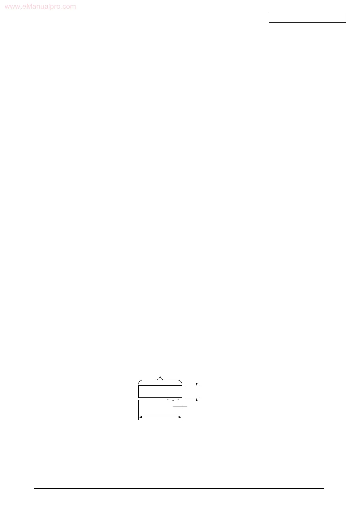
1 Information written
From left: One asterisk (*) character
Four-digit date (ID barcode) system
One-digit year (only one-digit x of 200x)
One-digit month (X, Y and X, for Oct., Nov. and Dec.)
Two-digit day
Four digits Filled with zeros 0000
Two-digit correction value
(In the same format as that for data manually input to printer)
00 to 04, for 0 to 4. FF to FC, for -1 to -4.
xxx.......xx FC
Approx.31 mm
2-Character correction value
Code content
6mm
 Loading...