Field Service Ver. 2.0 Jul. 2009 12. SERVICE MODE
465
ADJUSTMENT / SETTING
12.4.5 Printer Area-Leading Edge Adjustment
A. Use
• To vary the print start position in the sub scan direction for each of different paper types.
(To adjust the timing where paper is sent out from the timing roller)
• The PH unit has been replaced.
• The paper type has been changed.
• The print image deviates in the sub scan direction.
• A faint image occurs on the leading edge of the image.
• This setting can be made independently for plain paper, Thick 1/1+, Thick 2, Thick 3,
Thick 4, OHP transparencies, and envelopes.
B. Procedure
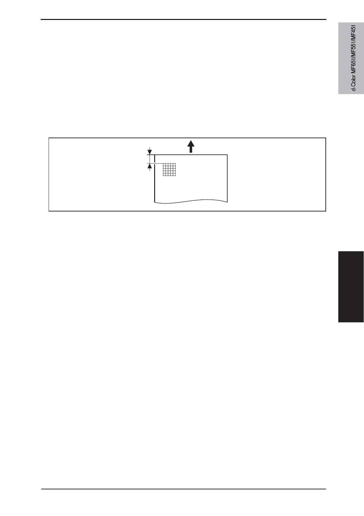
• Width A on the test pattern produced should fall within the following range.
Specifications: 4.2 r 0.5 mm
1. Place A3 paper on the manual bypass tray.
2. Call the Service Mode to the screen.
3. Touch [Machine] o [Printer Area] o [Leading Edge Adjustment].
4. Select the [Plain Paper].
5. Press the Start key to let the machine produce a test print.
6. Check the dimension of width A on the test print.
7. If width A falls outside the specified range, change the setting using the [+] / [-] key.
If width A is longer than the specifications, make the setting value smaller than the cur-
rent one.
If width A is shorter than the specifications, make the setting value greater than the cur-
rent one.
8. Press the Start key to let the machine prod
uce a test print.
9. Check the dimension of width A on the test print.
10. If width A is outside the specified range, change the setting again and make a check
again.
11. If width A falls within the specified range, touch [END].
12. Following the same procedure, adjust for Thick 1 to 3, OHP film, and Enve.
A0P0F3C503DA
Width A
Y110571-1 Service Manual
 Loading...