19. TROUBLE CODE Field Service Ver. 2.0 Jul. 2009
792
TROUBLESHOOTING
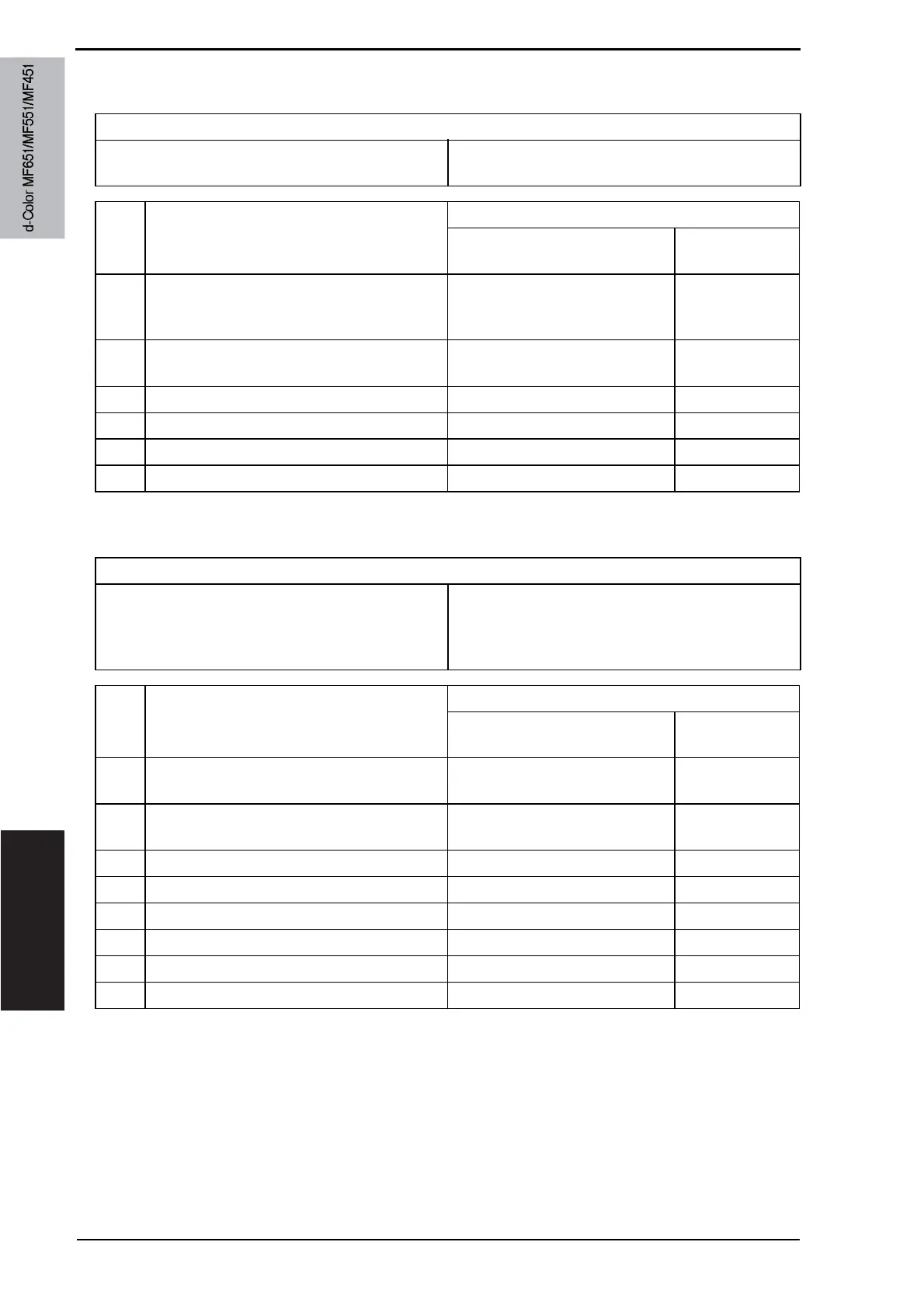
19.5.61 C11E2: Tray1 path switching motor drive malfunction
19.5.62 C2101: PC charge cleaning malfunction
Relevant parts
Tray1 path switching motor (M8)
Tray1 path switching home sensor (PS7)
FS control board (FSCB)
Step Action
WIRING DIAGRAM
Control signal
Location (Electri-
cal component)
1
Check the motor and sensor connectors for
proper connection, and correct as neces-
sary.
——
2
Check the connector of M8 for proper drive
coupling, and correct as necessary.
——
3 PS7 I/O check, sensor check FSCB PJ16-3 (ON) FS-527 J-5
4 M8 operation check FSCB PJ9-4 (REM) FS-527 J-2
5 Change M8 — —
6 Change FSCB — —
Relevant parts
Drum unit /K
Charging cleaner home sensor (PS43)
Charging cleaner return sensor (PS44)
Charge cleaning motor/K (M15)
Printer control board (PRCB)
Step Action
WIRING DIAGRAM
Control signal
Location (Electri-
cal component)
1 Check the drum unit/K for proper connec-
tion and correct as necessary.
——
2 Check the M15 connector for proper con-
nection and correct as necessary.
——
3 PS43 I/O check, sensor check PRCB CN25-11 (ON) C-12
4 PS44 I/O check, sensor check PRCB CN25-14 (ON) C-12
5 M15 operation check PRCB CN8-1 to 2 C-12
6 Change drum unit /K — —
7 Change M15 — —
8 Change PRCB — —
Service Manual Y110571-1
 Loading...