93
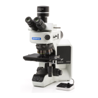
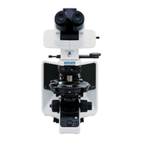
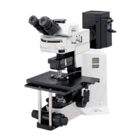
BX53M
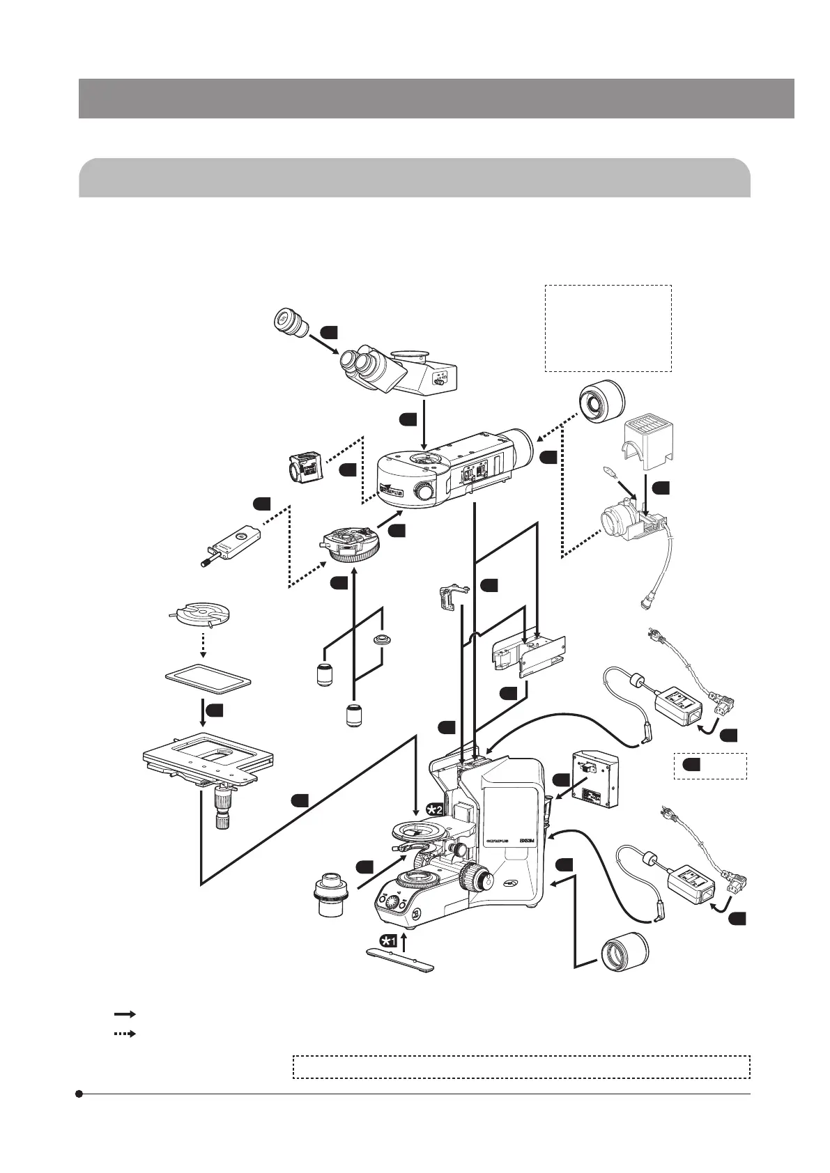
88 Assembly
8-1 Assembly diagram
The numbers in the following diagram represent the order to attach each unit.
The units shown in the following diagram are typical examples. For combination of units, contact Olympus or refer to the
latest catalogs. (In order to ensure the performance, ask Olympus to attach/detach the units.)
: Can be combined.
: May not be combined depending on units.
Observation
tube
Intermediate attachment
U-DP U-DP1XC
U-ECA U-CA
U-EPA2 U-CPA
U-OPA U-TRU
U-KPA
17
Cables
Eyepiece
MIX slider / DIC slider
for reflected light
observation
Fluorescence
mirror unit
Stage
Condenser
Stage plate
Stage option
Brightfield
objective
Microscope frame
BX53MRF-S
BX53MTRF-S
Light source
for transmitted light illumination
Light source for reflected
light illumination
Reflected light
illuminator
Power cord
Height adapter
Brightfield/
darkfield
objective
Brightfield
objective
adapter
Cable for
motorized
nosepiece
Control box
Nosepiece
AC adapter
For the polarization observation, refer to the instruction manual provided with the unit.
2
3
1
7
6
5
4
8
10
9
11
13
12
14
15
16
18
Overturning prevention
plate
18
AC adapter