part
2
S
ETUP
12
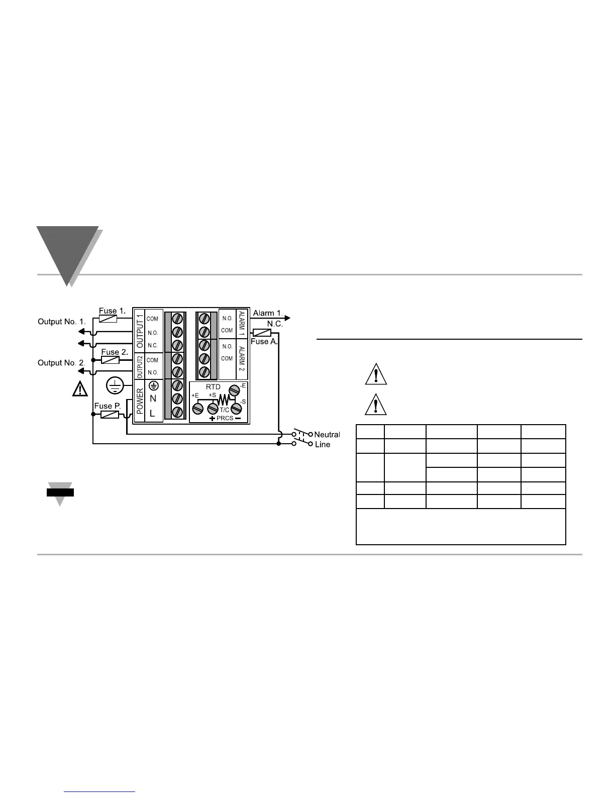
2.5. Electrical Installation
POWER CONNECTION EXAMPLES
The figure below shows the power wiring hookup.
Fuse Connector Output Type 115 Vac 230 Vac
Fuse 1 Output 1 Relay 5 A(T) 3 A(T)
Fuse 2 Output 1 Relay 5 A(T) 3 A(T)
SSR 0.5 A(T) 0.5 A(T)
Fuse P Power N/A 100 mA(T) 100 mA(T)
Fuse A Alarm 1/2 Relay 3 A(T) 3 A(T)
Note: Values shown are minimum recommendations for the
protection of the controller. For a specific load, consult the respected
electrical specifications to select a suitable fuse.
The Protective Conductor terminal must be
connected for safety reasons.
The Safety European Standard EN61010-1 for measurement, control, and laboratory
equipment requires that fuses must be specified based on IEC127. This standard
specifies for a Time-lag fuse, the letter code ÒTÓ. The above recommended fuses are
of the type IEC127-2-sheet III. Be aware that there are significant differences
between the requirements listed in the UL 248-14/CSA 248.14 and the IEC 127 fuse
standards. As a result, no single fuse can carry all approval listings. A 1.0 Amp IEC
fuse is approximately equivalent to a 1.4 Amp UL/CSA fuse. It is advised to consult
the manufacturerÕs data sheets for a cross-reference.
Use copper conductors only for power
connections
Figure 2.5.1 Power Wiring Hookup

 Loading...


