part
2
S
ETUP
14
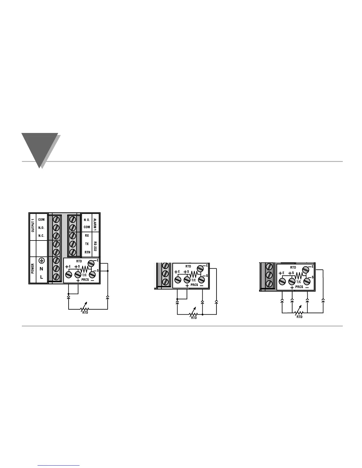
The figures below show the input connections and input connector jumpers
required to hookup a 2, 3 or 4-wire RTD.
The two-wire connection is the simplest method, but does not compensate for lead-
wire temperature change and often requires calibration to cancel lead-wire resistance
offset.
The three-wire connection works best with RTD leads closely equal in
resistance. The controller measures the RTD, plus upper and lower lead drop
voltage and then subtracts twice the measured drop in the lower supply current
lead producing excellent lead-resistance cancellation for balanced
measurements.
The four-wire RTD hookup is applicable to unbalanced lead resistance and
enables the controller to measure and subtract the lead voltage which produces
the best lead-resistance cancellation.When configuring your controller, select
RTD type and RTD value in the Input Type Menu (see part 3).
2.5.2. Two/Three/Four-Wire RTD
Figure 2.5.3
Two-Wire RTD Hookup
Three-Wire RTD Hookup
Four-Wire RTD Hookup

 Loading...


