PLATINUM
TM
Series Controllers User’s Guide
M5451 Omega Engineering | www.omega.com
3.3 Connecting Inputs
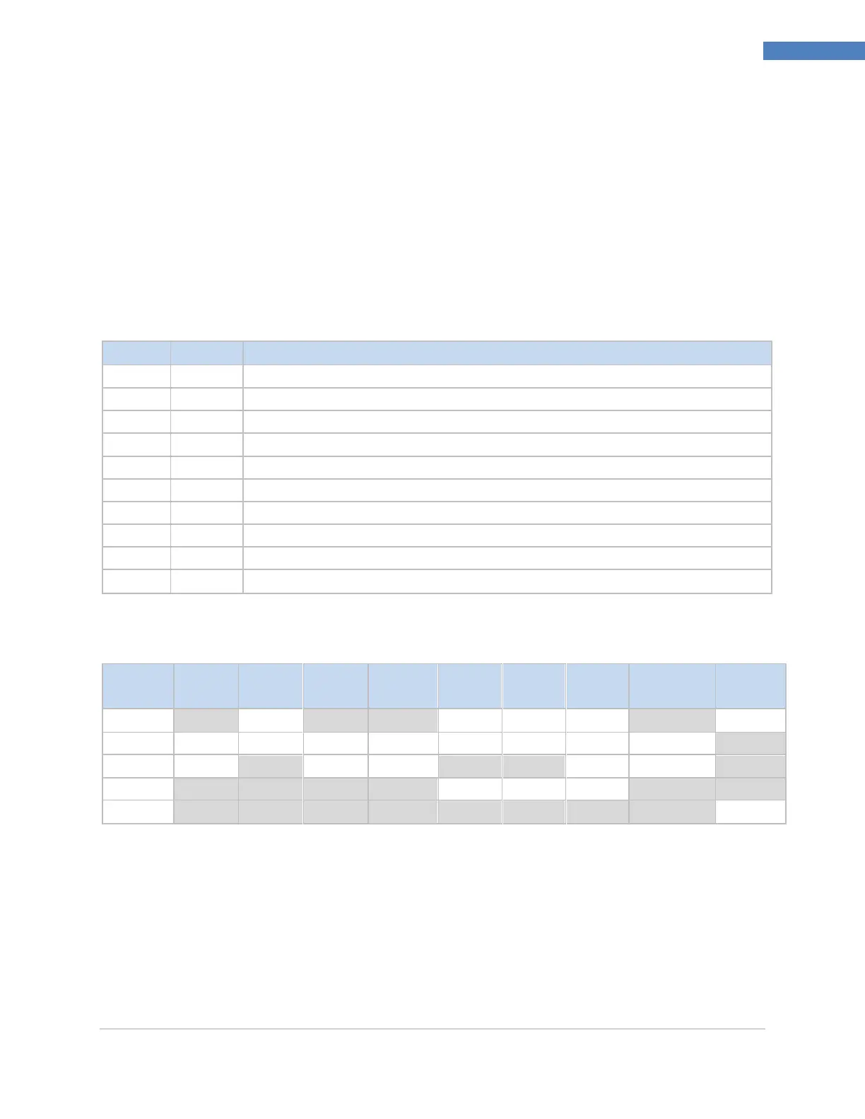
The 10-pin universal input connector assignments are summarized in Table 1. Table 2 provides detail for
the specific types of sensors supported. All sensor selections are firmware-controlled (see 4.1 Input
Configuration (INIt > INPt)) and no jumper settings are required when switching from one type of sensor
to another. Figure 5 provides more detail for connecting RTD sensors. Figure 6 shows the connection
scheme for process current input with either internal or external excitation. Figure 7 shows the
connections for Single Ended and Differential input voltages.
Table 1 – 10-Pin Input Connector Wiring Summary
Analog return signal (analog ground) for sensors and remote Setpoint
Analog power currently only used for 4-wire RTDs
Auxiliary analog input for remote Setpoint
Excitation voltage output referenced to ISO GND
Digital input signal (latch reset, etc.), Positive at > 2.5V, ref. to ISO GND
Isolated ground for serial communications, excitation, and digital input
Serial communications receive
Serial communications transmit
Table 2 – Interfacing Sensors to the Input Connector
*For Remote Setpoint with an RTD, Pin 1 on the Output Connector must be used for the RtN instead of Pin 1 on the
Input Connector. Remote Setpoint is not available if using an RTD sensor and have an SPDT (Type 3) Output
installed.
** Requires external connection to pin 4

 Loading...


