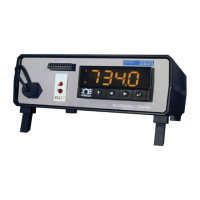
PLATINUM
TM
Series Controllers User’s Guide
M5451 Omega Engineering | www.omega.com
Table of Contents, Figures and Tables
1. Introduction .......................................................................................................................................... 8
1.1 Description .................................................................................................................................... 8
2. Safety Considerations ........................................................................................................................... 9
3. Wiring Instructions ............................................................................................................................. 10
3.1 Back Panel Connections .............................................................................................................. 10
3.2 Connecting Power ....................................................................................................................... 11
3.3 Connecting Inputs ....................................................................................................................... 12
3.4 Connecting Outputs .................................................................................................................... 14
4. PLATINUM
TM
Series Navigation .......................................................................................................... 16
4.1 Description of Button Actions ..................................................................................................... 16
4.2 Menu Structure ........................................................................................................................... 16
4.3 Level 1 Menu ............................................................................................................................... 17
4.4 Circular Flow of Menus ............................................................................................................... 17
5. Complete Menu Structure .................................................................................................................. 18
5.1 Initialization Mode Menu (INIt) .................................................................................................. 18
5.2 Programming Mode Menu (PRoG) ............................................................................................. 22
5.3 Operating Mode Menu (oPER) .................................................................................................... 25
6. Reference Section: Initialization Mode (INIt) ..................................................................................... 27
6.1 Input Configuration (INIt > INPt) ................................................................................................. 27
6.1.1 Thermocouple Input Type (INIt > INPt > t.C.) ..................................................................... 27
6.1.2 Resistance Temperature Detector (RTD) Input Type (INIt > INPt > Rtd) ............................ 28
6.1.3 Thermistor Input Type Configuration (INIt > INPt > tHRM) ................................................ 28
6.1.4 Process Input Type Configuration (INIt > INPt > PRoC) ....................................................... 29
6.2 TARE (INIt > tARE) ....................................................................................................................... 34
6.3 LINR (INIt > LINR) ......................................................................................................................... 34
6.4 Display Reading Formats (INIt > RdG) ......................................................................................... 36
6.4.1 Decimal Point Format (INIt > RdG > dEC.P) ......................................................................... 36
6.4.2 Temperature Units (INIt > RdG > °F°C) ................................................................................ 36
6.4.3 Display Rounding (INIt > RdG > d.RNd) ............................................................................... 37
6.4.4 Filter (INIt > RdG > FLtR) ...................................................................................................... 37
6.4.5 Annunciator Settings (INIt > RdG > ANN.1/ANN.2) ............................................................. 38
6.4.6 Normal Color (INIt > RdG > NCLR) ....................................................................................... 38
6.4.7 Brightness (INIt > RdG > bRGt) ............................................................................................ 38
6.5 Excitation Voltage (INIt > ECtN) .................................................................................................. 39
6.6 Communication (INIt > CoMM) ................................................................................................... 39
6.6.1 Protocol (INIt > CoMM > USb, EtHN, SER > PRot) ............................................................... 39
6.6.2 Address (INIt > CoMM > USb, EtHN, SER > AddR) ............................................................... 40
6.6.3 Serial Communications Parameters (INIt > CoMM > SER >C.PAR) ..................................... 41
6.7 Safety Features (INIt > SFty) ........................................................................................................ 42
6.7.1 Power On Confirmation (INIt > SFty > PwoN) ..................................................................... 42
6.7.2 Operating Mode Confirmation (INIt > SFty > oPER) ............................................................ 42
6.7.3 Setpoint Limits (INIt > SFty > SP.LM) ................................................................................... 43
6.7.4 Loop Break Timeout (INIt > SFty > SEN.M > LPbk) .............................................................. 43
6.7.5 Open Circuit (INIt > SFty > SEN.M > o.CRk) ......................................................................... 43
6.7.6 Sensor Error Latch (INIt > SFty > SEN.M > E.LAT) ................................................................ 43
6.7.7 Output Break detection (INIt > SFty > OUT.M > o.bRK) ...................................................... 44

 Loading...