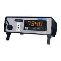
PLATINUM
TM
Series Controllers User’s Guide
M5451 Omega Engineering | www.omega.com
6.7.8 Output Error Latch (INIt > SFty > OUT.M > E.LAT) .............................................................. 44
6.8 Manual Temperature Calibration (INIt > t.CAL) .......................................................................... 44
6.8.1 No Manual Temperature Calibration Adjustment (INIt > t.CAL > NoNE)............................ 45
6.8.2 Manual Temperature Calibration Offset Adjustment (INIt > t.CAL > 1.PNt) ...................... 45
6.8.3 Manual Temperature Calibration Offset and Slope Adjustment (INIt > t.CAL > 2.PNt) ...... 45
6.8.4 Temperature Ice Point Calibration (INIt > t.CAL > ICE.P) .................................................... 46
6.9 Save Current Configuration for All Parameters to a File (INIt > SAVE) ....................................... 46
6.10 Load a Configuration for All Parameters from a File (INIt > LoAd) ............................................. 46
6.11 Display Firmware Revision Number (INIt > VER.N) ..................................................................... 46
6.12 Update Firmware Revision (INIt > VER.U) ................................................................................... 47
6.13 Reset to Factory Default Parameters (INIt > F.dFt) ..................................................................... 47
6.14 Password-Protect Initialization Mode Access (INIt > I.Pwd) ....................................................... 47
6.15 Password-Protect Programming Mode Access (INIt > P.Pwd) .................................................... 47
7. Reference Section: Programming Mode (PRoG) ................................................................................ 48
7.1 Setpoint 1 Configuration (PRoG > SP1) ....................................................................................... 48
7.2 Setpoint 2 Configuration (PRoG > SP2) ....................................................................................... 48
7.3 Alarm Mode Configuration (PRoG > ALM.1, ALM.2)................................................................... 49
7.3.1 Alarm Type (PRoG > ALM.1, ALM.2 > tyPE)......................................................................... 49
7.3.2 Absolute or Deviation Alarm (PRoG > ALM.1, ALM.2 > tyPE > Ab.dV) ................................ 50
7.3.3 Alarm High Reference (PRoG > ALM.1, ALM.2 > tyPE > ALR.H) .......................................... 50
7.3.4 Alarm Low Reference (PRoG > ALM.1, ALM.2 > tyPE > ALR.L) ............................................ 51
7.3.5 Alarm Color (PRoG > ALM.1, ALM.2 > A.CLR) ...................................................................... 51
7.3.6 Alarm High High / Low Low Offset Value (PRoG > ALM.1, ALM.2 > HI.HI) ......................... 51
7.3.7 Alarm Latching (PRoG > ALM.1, ALM.2 > LtCH) .................................................................. 52
7.3.8 Alarm Normally Closed, Normally Open (PRoG > ALM.1, ALM.2 > CtCL) ........................... 52
7.3.9 Alarm Power-On Behavior (PRoG > ALM.1, ALM.2 > A.P.oN) ............................................. 52
7.3.10 Alarm on Delay (PRoG > ALM.1, ALM.2 > dE.oN) ................................................................ 52
7.3.11 Alarm Off Delay (PRoG > ALM.1, ALM.2 > dE.oF) ............................................................... 53
7.4 Output Channel 1–6 Configuration (PRoG > oUt.1–oUt.6) ......................................................... 53
7.4.1 Output Channel Mode (PRoG > oUt1–oUt6 > ModE) ......................................................... 54
7.4.2 Output Cycle Pulse Width (PRoG > oUt1–oUt6 > CyCL) ...................................................... 56
7.4.3 Analog Output Range (PRoG > oUt1–oUt6 > RNGE) ........................................................... 57
7.5 PID Configuration (PRoG > PId.S) ................................................................................................ 58
7.5.1 Action Response (PRoG > PId > ACtN) ................................................................................ 58
7.5.2 Autotune Timeout (PRoG > PId > A.to) ............................................................................... 58
7.5.3 Autotune (PRoG > PId > TUNE) ........................................................................................... 58
7.5.4 PID Gain Settings (PRoG > PId > GAIN) ................................................................................ 59
7.5.5 Relative Cool Gain (PRoG > PId > rCg) ................................................................................. 60
7.5.6 Control Offset (PRoG > PId > oFst) ...................................................................................... 60
7.5.7 Deadband (PRoG > PId > dEAd) ........................................................................................... 60
7.5.8 Low Output Clamping Limit (PRoG > PId > %Lo) ................................................................. 60
7.5.9 High Output Clamping Limit (PRoG > PId > %HI) ................................................................ 61
7.5.10 Adaptive Tuning (PRoG > PId > AdPt) ................................................................................. 61
7.6 PID.2 Configuration (PRoG > PId.2) ............................................................................................. 61
7.7 Remote Setpoint Configuration (PRoG > RM.SP) ........................................................................ 61
7.7.1 Cascade Control using Remote Setpoint ............................................................................. 63
7.8 Multi-Ramp/Soak Mode Parameters (PRoG > M.RMP) .............................................................. 64
7.8.1 Multi-Ramp/Soak Mode Control (PRoG > M.RMP > R.CtL) ................................................. 64

 Loading...