EasyManua.ls Logo

Omega PLATINUM Series - Page 15

Omega PLATINUM Series
79 pages
To Next Page IconTo Next Page
To Previous Page IconTo Previous Page
Loading...
PLATINUM
TM
Series Controllers User’s Guide
M5451 Omega Engineering | www.omega.com
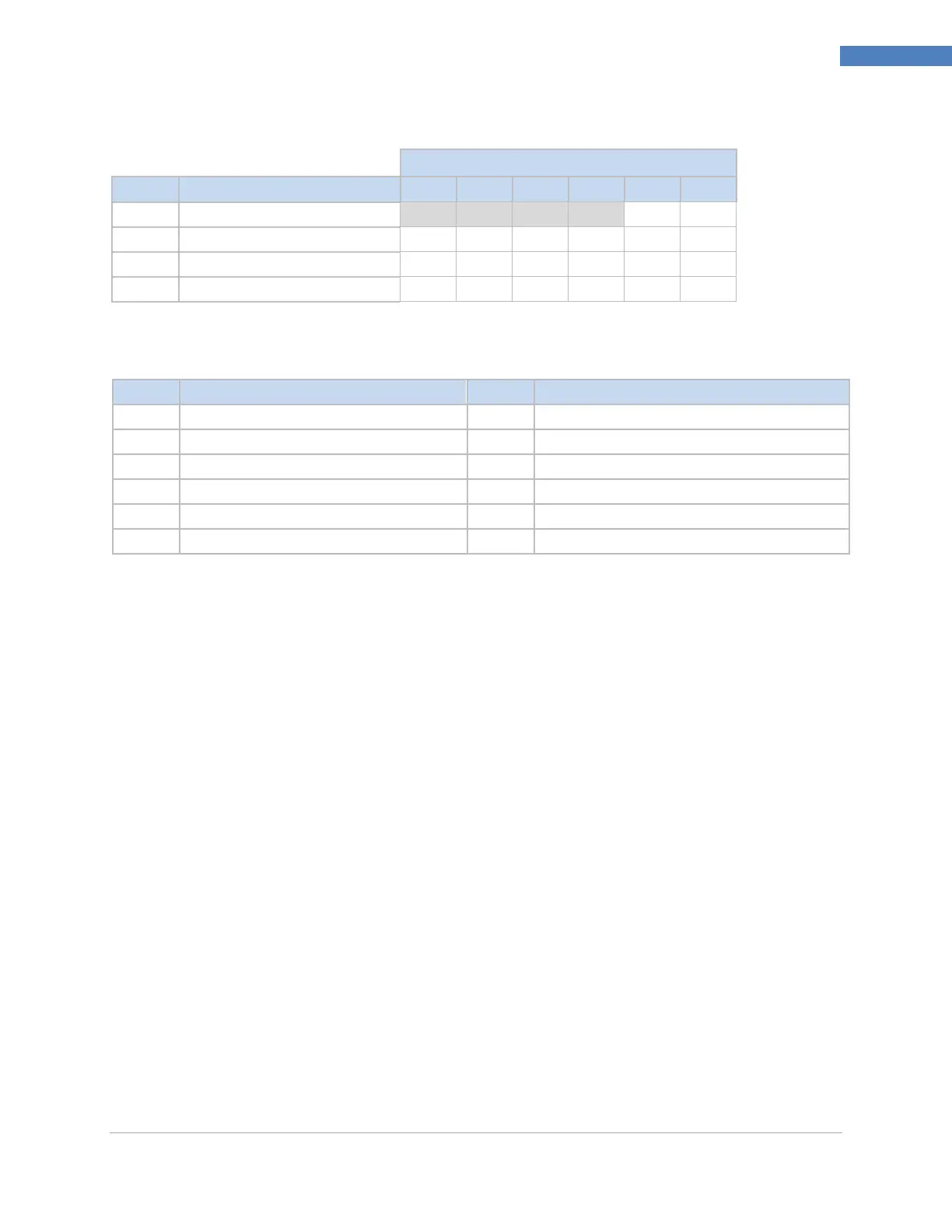
15
Wiring Instructions
Table 5 6 Pin Output Expansion Board Connector Wiring Summary by Configuration.
Output Expansion Board Pin Number
Config.
Description
6
5
4
3
2
1
006
Isolated Analog
V/C+
Gnd
776
IDC, IDC, Isolated Analog
V+
Gnd
V+
Gnd
V/C+
Gnd
116
SPST, SPST, Isolated Analog
N.O
Com
N.O
Com
V/C+
Gnd
226
SSR, SSR, Isolated Analog
N.O
Com
N.O
Com
V/C+
Gnd
Table 6 Definitions for Abbreviations in Table 4.
Code
Definition
Code
Definition
N.O.
Normally open relay/SSR load
AC-
AC power neutral in pin
Com
Relay Common/SSR AC power
AC+
AC power hot in pin
N.C.
Normally closed relay load
DC-
Negative DC power in pin
Gnd
DC Ground
DC+
Positive DC power in pin
V+
Load for DC pulse
V/C+
Load for analog

Table of Contents

Related product manuals