CP TD1 Reference Manual V 1.44
172
In Figure 12-28, the serial connected C1 and R1 represent the test object with
losses, C2 the loss-free reference capacitor. The parallel circuit diagram in
Figure 12-26 can be transferred as a direct equivalent into this serial diagram at
specified frequencies. The new test system utilizes a method similar to that of
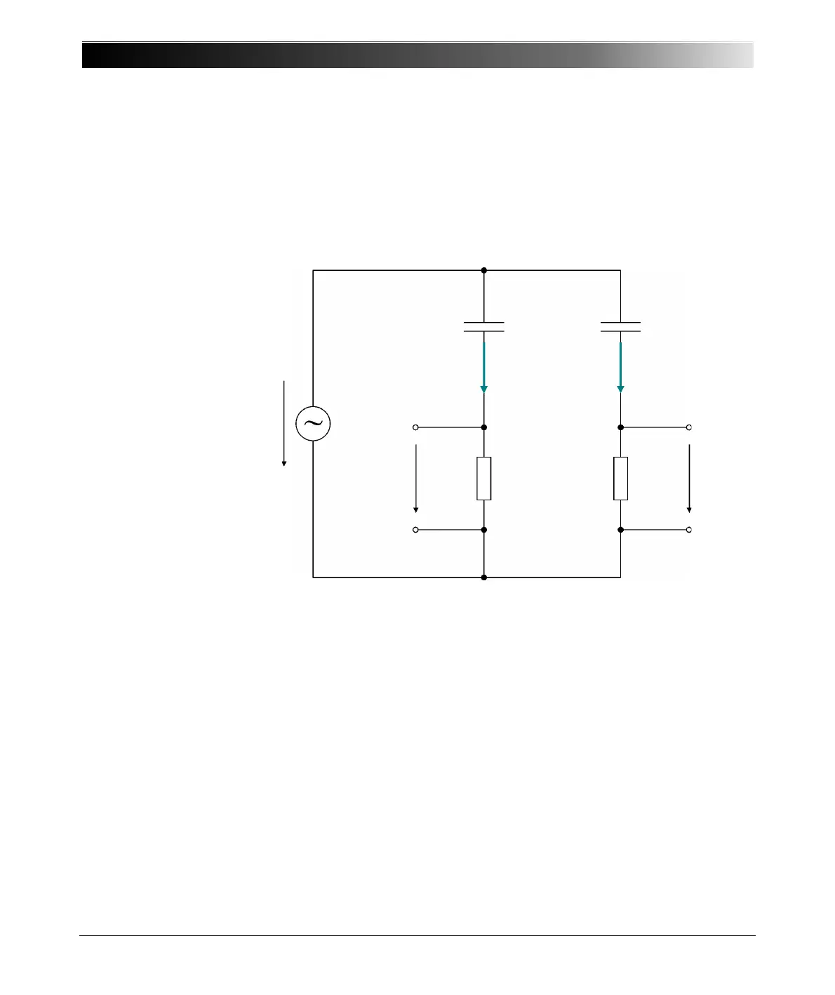
the Schering bridge. The main difference is that the system described in Figure
12-29 doesn't require tuning for measuring C and DF. Cn is a gas insulated
reference capacitor with losses below 10E-5.
Figure 12-29 CP TD1 measuring principle
For laboratory use, such capacitors are regularly used to obtain precise
measurements, as the climatic conditions are very constant. This is not the case
for on-site measurements where temperatures can vary significantly, which
leads to extension and contraction of the electrode length in the reference
capacitor. The test system takes all these effects into account and compensates
U
0
(t)
U
N
(t) U
X
(t)Z
1
Z
2
I
CN
I
CX
Z
N
C
X
Z
X
, L
X
C
N
Reference path Measurement path

 Loading...


