CP TD1 Reference Manual V 1.44
74
As shown in Figure 6-2, the three phases of the high-voltage (H), the low-voltage
(L) and the tertiary (T) windings are connected internally in y or delta. This way
only the sum of all three phases can be measured, the single phases can not be
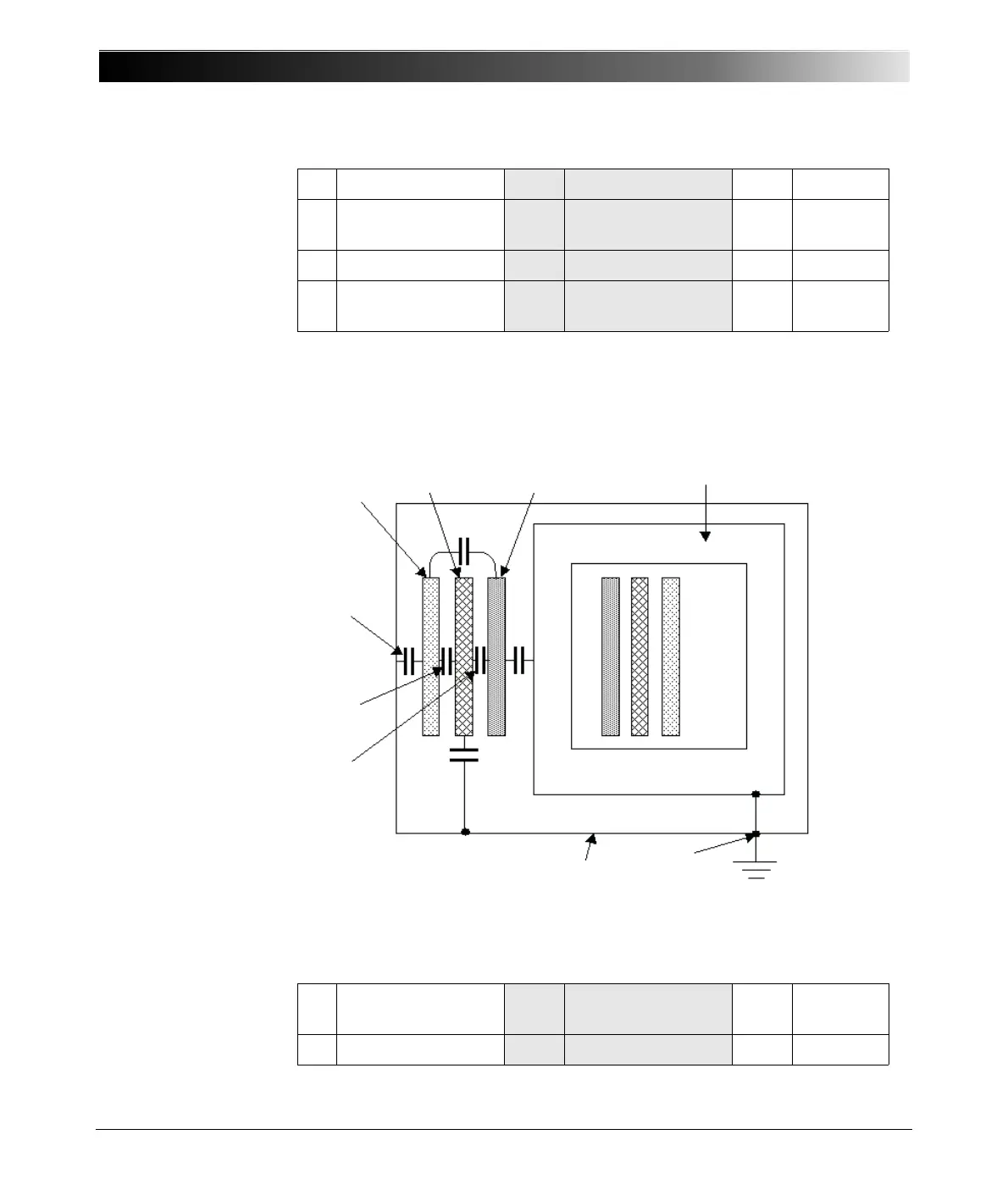
measured separately. Figure 6-3 shows the simplified circuit diagram of the
three-phase transformer of Figure 6-2.
Figure 6-3 Three-phase transformer with winding capacitances
A Phase A B Phase B C Phase C
H High-Voltage
winding
C H Cap. H to Ground C H-L Cap. H to
L
L Low-Voltage winding C L Cap. L to Ground C L-T Cap. L to T
T Tertiary winding C T Cap. T to Ground C H-T Cap. H to
T
H High-Voltage
winding
C H Cap. H to Ground C H-L Cap. H to
L
L Low-Voltage winding C L Cap. L to Ground C L-T Cap. L to T
Core
Tank
G
C
L-T
C
H-L
C
H
C
T
C
L
H
LT

 Loading...


