OMICRON 27
Application
1. Ensure that the Control Device is switched off at the mains power switch.
2. Without trolley:
► Properly connect the Control Device and CP TD1 grounding terminals to substation ground.
With trolley (optional):
► Connect the trolley’s ground bar to earth.
► Properly connect the CPC 100 or TESTRANO 600 and CP TD1 grounding terminals to the
trolley’s ground bar.
3. Make sure that all cable connectors are clean and dry before being tightly connected.
4. Connect the CP TD1’s "BOOSTER IN" to the Control Device’s "EXT. BOOSTER" with the booster
cable.
5. Connect the CP TD1’s "SERIAL" to the Control Device’s "SERIAL" with the data cable. This cable
also provides the power supply for the CP TD1.
6. Pull out the measuring cables from the cable drum and connect the test object to the CP TD1’s
measuring inputs IN A and IN B.
7. Connect the high-voltage cable from the test object to the CP TD1’s high-voltage output.
►At the CP TD1, press the high-voltage cable’s plug to the connector tightly and turn the screw cap
manually without using any tools until you feel a mechanical stop. If you notice a rough-running of
the screw-cap, clean the screw thread and use a lubricant (Vaseline recommended).
► Insert the yellow banana plug (the high-voltage cable’s grounding) into the respective plug socket.
► At the test object, insert the high-voltage cable’s plug carefully until you feel a "click" position. Now
they are locked. Confirm this by trying to pull them out. This should not be possible now.
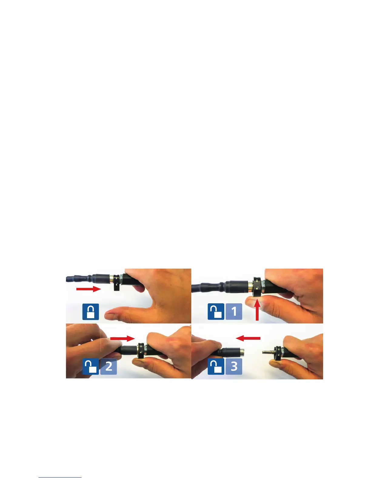
The images below show how to unlock the cable connection again. This is also shown on a label
fixed to the high-voltage cable.
► After the HV cable connection is established, use the strain relieve delivered with the HV cable to
fasten it to the test object.

 Loading...


