CP TD1 User Manual
64 OMICRON
7 Technical data
7.1 Technical data of the CP TD1 in combination with the
Control Device
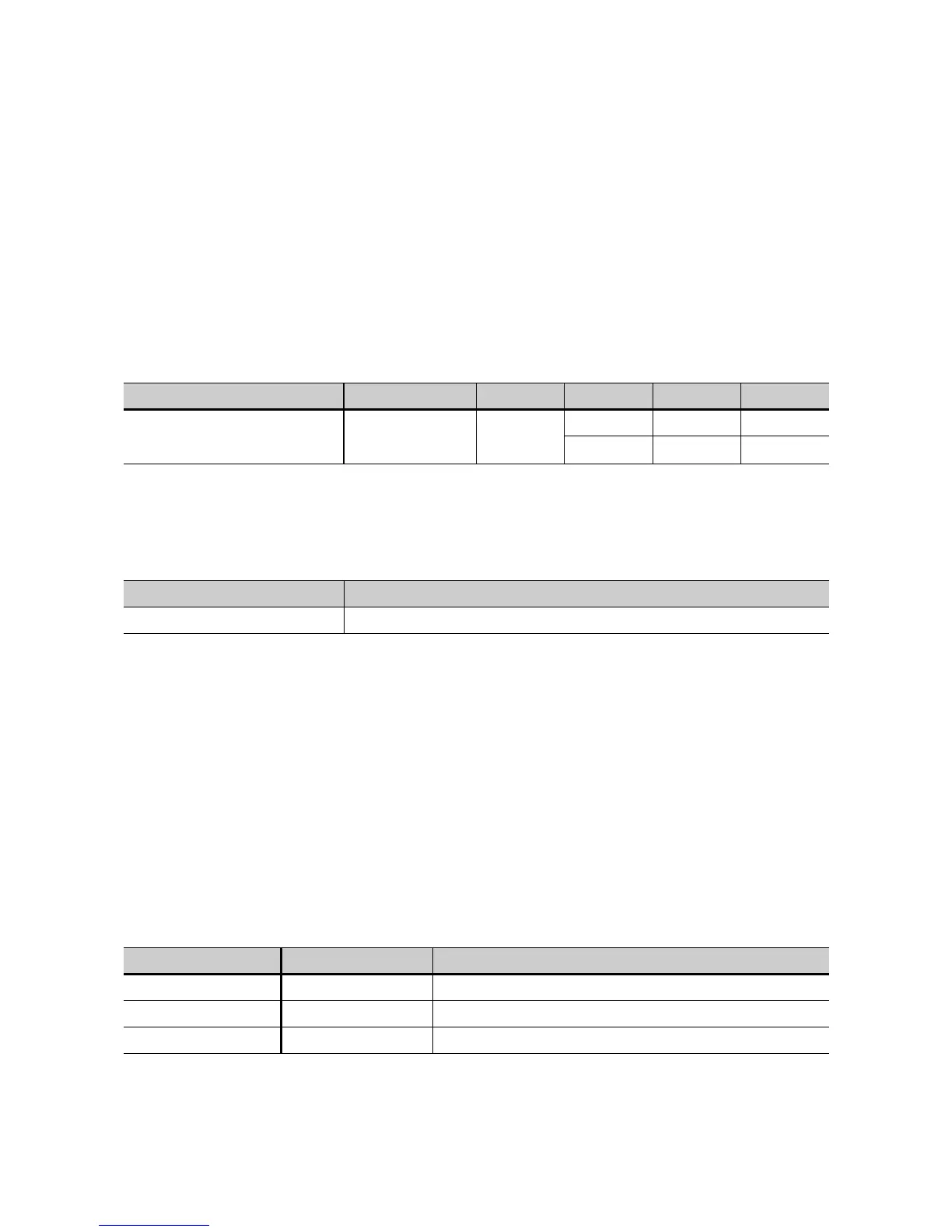
7.1.1 High-voltage output
Conditions: Signals below 45 Hz with reduced values possible. Capacitive linear loads.
7.1.2 Measurements
Test frequencies
Only CPC 100 and CPC 80: TanDelta test card: Column "Hz" of the results table
Special displays in the frequency column "Hz" and their meanings:
Filter for selective measurements
Conditions: f = 15 ... 400 Hz
Table 7-1: High-voltage output
Terminal U / f THD I S t
max
High-voltage output
0...12 kV AC
15...400 Hz
< 2 %
300mA 3600VA > 2min
100mA 1200VA > 60min
Table 7-2: Test frequencies
Range Typical accuracy
15...400 Hz error < 0.005 % of reading
*50 Hz (*60 Hz) Measurement mode suppressing the mains frequency interferences; doubles
the measurement time.
!30 Hz The selected test voltage is not available in Automatic measurement (applies to
frequencies below 45 Hz only).
?xx Hz Results with reduced accuracy, e.g., in case of a low testing voltage, influences
of partial discharge etc.
Table 7-3: Filter for selective measurements
Filter Bandwidth Measurement time Stop band specification (attenuation)
f0 ± 5 Hz 2.2 s > 110 dB at fx = f0 ± (5 Hz or more)
f0 ± 10 Hz 1.2 s > 110 dB at fx = f0 ± (10 Hz or more)
f0 ± 20 Hz 0.9 s > 110 dB at fx = f0 ± (20 Hz or more)

 Loading...


