CP TD1 User Manual
46 OMICRON
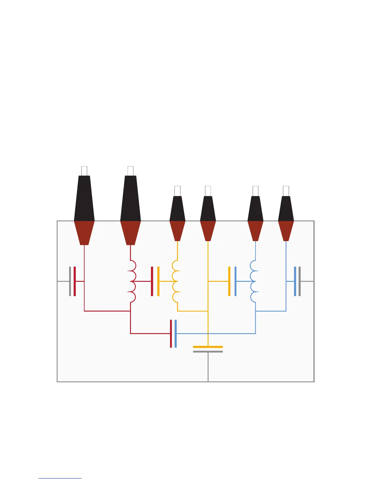
5.5 Three-winding transformer
In a three-winding transformer there are two parts of insulation which are formed by barriers and
spacers, C
HL
and C
LT
between the low- and tertiary-voltage windings (see Figure 5-8 below). Both
insulation parts are similar in construction to C
HL
in a two-winding transformer.
Additionally to insulation C
H
which is similar to C
H
in a two-winding transformer, there are insulation C
L
between the low-voltage winding and the tank, insulation C
T
between the tertiary winding and the tank
and insulation C
HT
between the high-voltage winding and the tertiary windings. C
T
is similar to C
L
in a
two-winding transformer, whereas C
L
in a three-winding transformer is mainly formed by the insulation
between the low-voltage winding and the tank and not the core limb. C
HT
is very small and usually not
of any specific importance as it is mainly formed by the stray capacitance from the HV side to the TV
side via the press construction above and below the windings.
Figure 5-8: Insulations of a three-winding transformer
All phases and the neutral terminal of one winding (H, L and T) have to be short-circuited. Due to the
inductance of the windings, resonant effects may occur and influence the measurement.

 Loading...


