OMICRON 19
Introduction
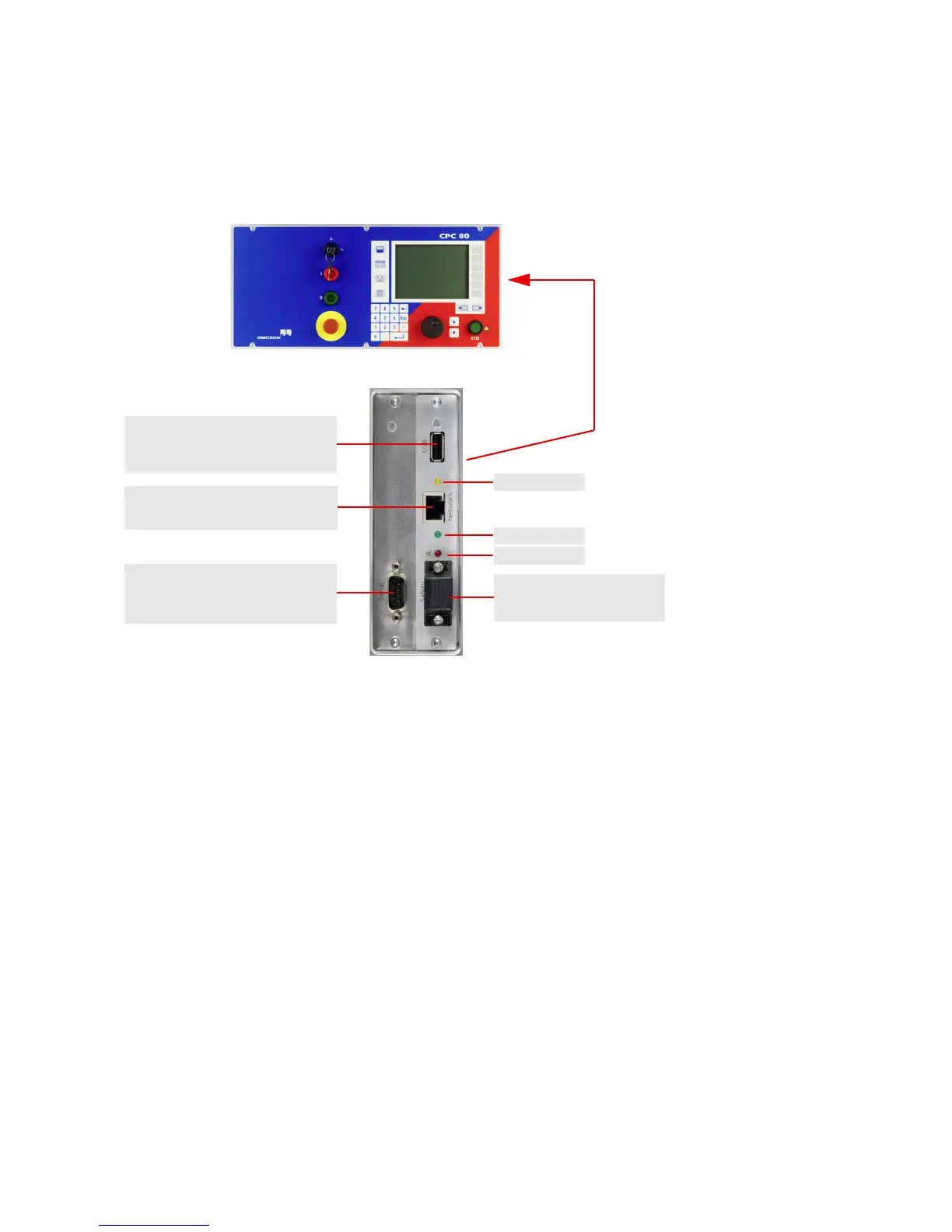
2.5.3 CPC 80 ePC Interfaces
The ePC interfaces are located on the right-hand side of the CPC 80 housing.
Figure 2-6: ePC interfaces of the CPC 80
The CPC 80 supports the USB interface 1.1 and 2.0 for connecting the USB memory stick shipped with
the CPC 80.
The full functionality is guaranteed only for the stick delivered with the CPC 80.
The network interface is an auto-crossover Ethernet connector that can be connected to a network hub
or directly to a PC or a notebook.
The CPC 80 provides the following LEDs on the ePC interface:
• Green LED lights if the CPC 80 is properly connected to a PC or network.
• Yellow LED lights if data is transferred from or to the network.
• Red LED serves for diagnosis purposes.
The connector for external safety functions allows connecting:
• an external Emergency Stop or "dead man" button
• an external "test start / stop" push-button
• external I / O warning lights.
The attached plug contains a jumper for the emergency stop or "dead man" function, and as long as the
plug is placed on the connector, these functions are bridged. If the plug is removed, emergency stop is
active.
Serial interface connector for
connecting the CP TD1
Connector for external safety
functions (see below)
Red LED
Yellow LED
Green LED
USB connector for connecting
OMICRON USB memory sticks
(see below)
RJ-45 socket for connecting the
CPC 80 to a PC or a network hub

 Loading...


