EasyManuals Logo

Omicron CP TD1 User Manual

Omicron CP TD1
70 pages
To Next Page IconTo Next Page
To Previous Page IconTo Previous Page
Page #23 background imageLoading...
Page #23 background image
OMICRON 23
Introduction
2.9 Functional components of the CP TD1
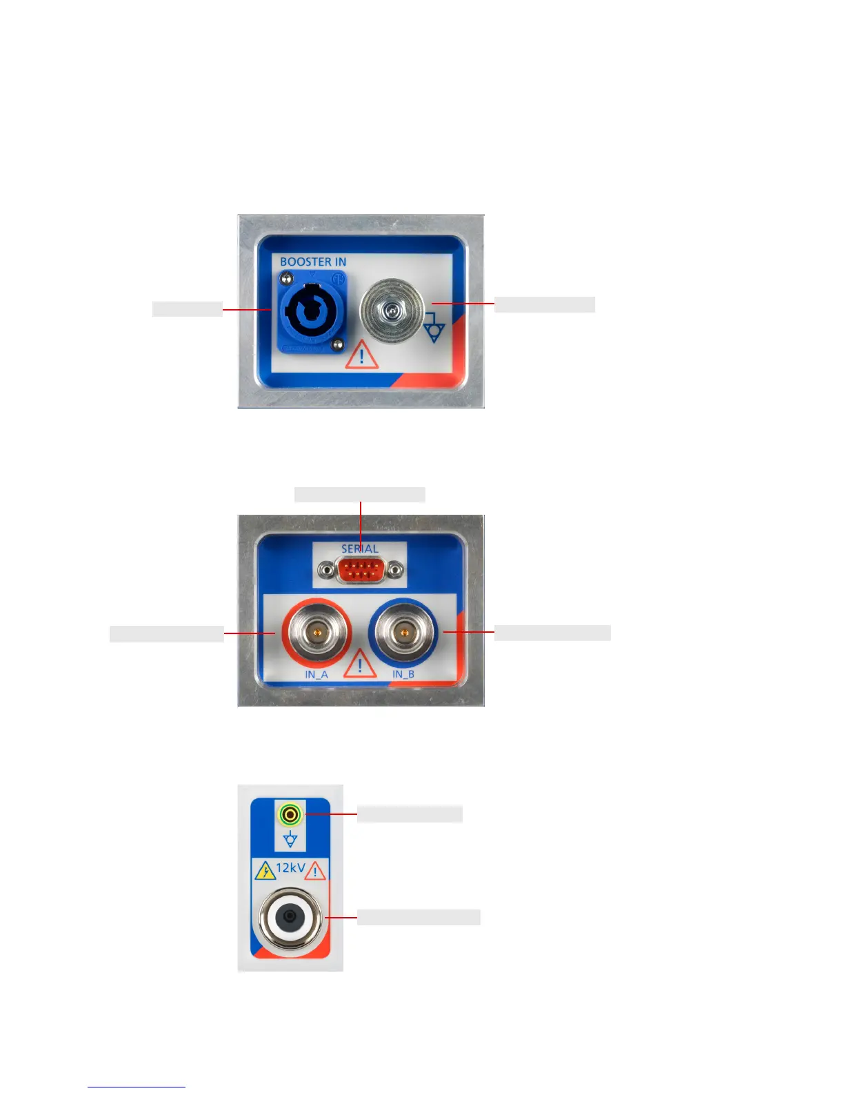
2.9.1 CP TD1 grounding terminal and Booster input
Figure 2-9: Grounding terminal and booster input of the CP TD1 (left side of the device)
2.9.2 CP TD1 serial interface connector and measuring inputs
Figure 2-10: Serial interface and measuring inputs of the CP TD1 (right side of the device)
2.9.3 CP TD1 high-voltage connector
Figure 2-11: High-voltage connector of the CP TD1 (rear of the device)
Grounding terminal
Booster input
Serial interface connector
IN_B measuring input
IN_A measuring input
High-voltage connector
Grounding terminal

Table of Contents

Other manuals for Omicron CP TD1

Questions and Answers:

Question and Answer IconNeed help?

Do you have a question about the Omicron CP TD1 and is the answer not in the manual?

Omicron CP TD1 Specifications

General IconGeneral
BrandOmicron
ModelCP TD1
CategoryMeasuring Instruments
LanguageEnglish

Related product manuals