OMICRON 65
Technical data
Test current (RMS, selective)
Test voltage (RMS, selective)
Capacitance Cp (equivalent parallel circuit)
Dissipation factor DF (tan δ)
Power factor PF (cos ϕ)
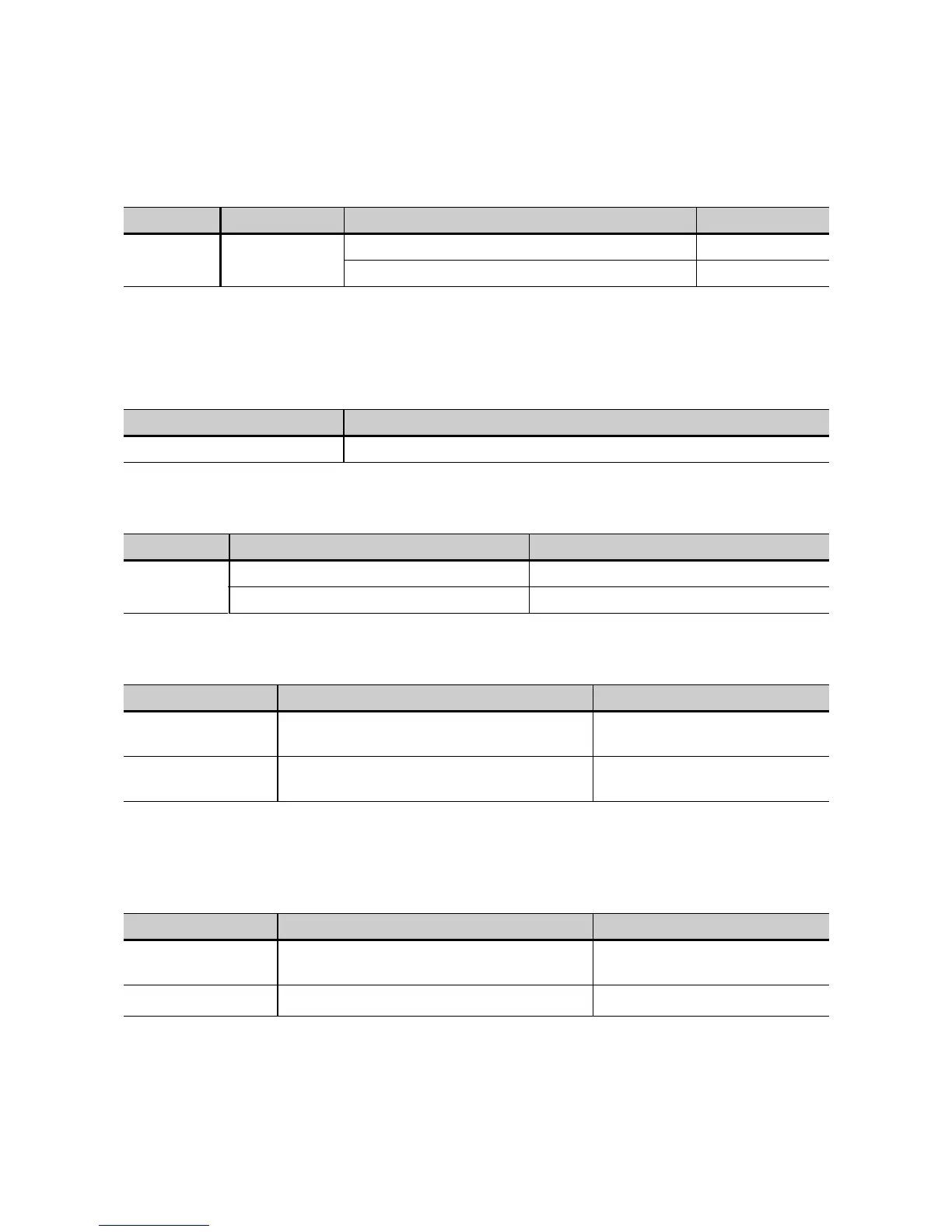
Table 7-4: Test current
Terminal Range Typical accuracy Conditions
IN A or
IN B
1
1. IN A (red) or IN B (blue), depending on the mode.
0...5 A AC
error < 0.3 % of reading + 100 nA Ix < 8 mA
error < 0.5 % of reading Ix > 8 mA
Table 7-5: Test voltage
Condition: U > 2 kV
Range Typical accuracy
0...12000 V AC error < 0.3 % of reading + 1 V
Table 7-6: Capacitance Cp
Range Typical accuracy Conditions
1 pF...3 µF
error < 0.05 % of reading + 0.1 pF Ix < 8 mA, Utest = 300 V...10 kV
error < 0.2 % of reading Ix > 8 mA, Utest = 300 V...10 kV
Table 7-7: Dissipation factor DF
Range Typical accuracy Conditions
0...10 % (capacitive)
error < 0.1 % of reading + 0.005 %
1
1. Reduced accuracy of DF at mains frequency or its harmonics. Mains frequency suppression available by precisely selecting
a mains frequency of *50Hz or *60Hz in the "Hz" column.
f = 45...70 Hz, I < 8 mA,
Utest = 300 V...10 kV
0...100
(0...10000 %)
error < 0.5 % of reading + 0.02 % Utest = 300 V...10 kV
Table 7-8: Power factor Pf
Range Typical accuracy Conditions
0...10 % (capacitive)
error < 0.1 % of reading + 0.005 %
1
1. Reduced accuracy of PF at mains frequency or its harmonics. Mains frequency suppression available by precisely selecting
a mains frequency of *50Hz or *60Hz in the "Hz" column.
f = 45...70 Hz, I < 8 mA,
Utest = 300 V...10 kV
0...100 %
error < 0.5 % of reading + 0.02 % Utest = 300 V...10 kV

 Loading...


