3-6-2
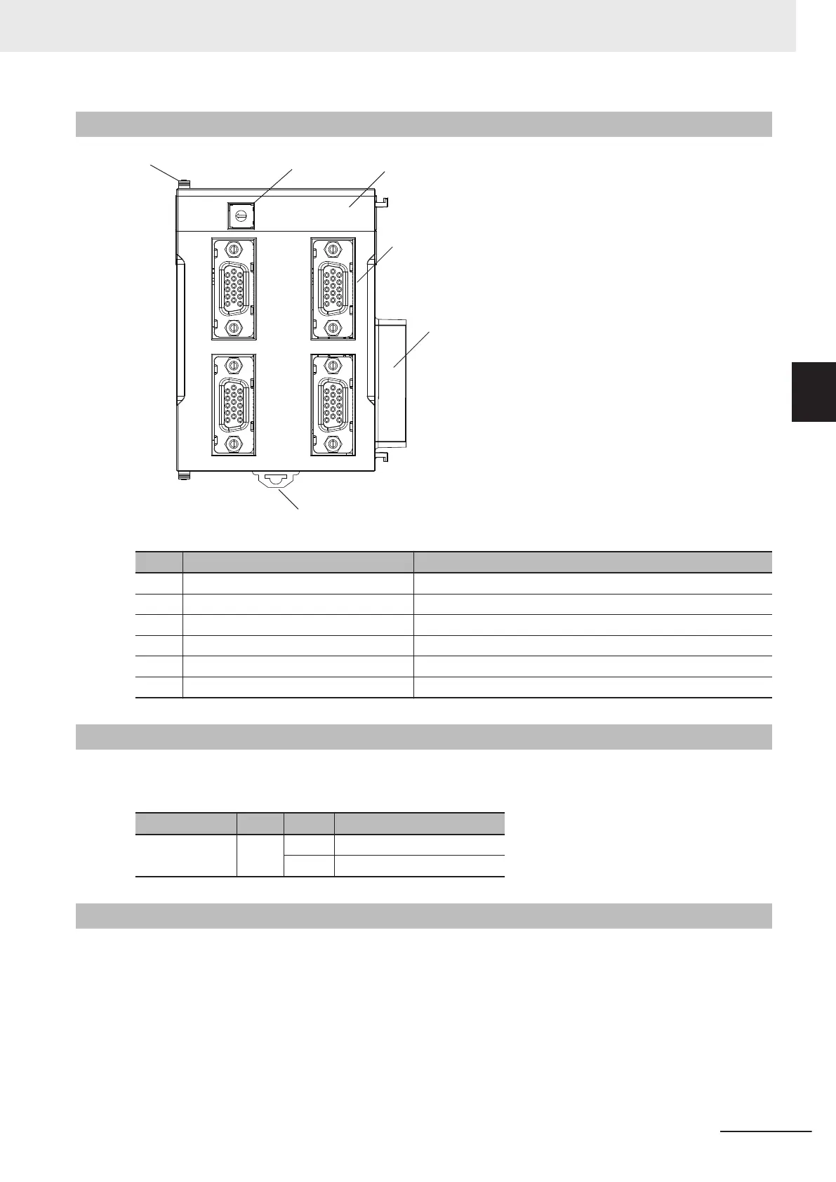
Part Names and Functions
ECS300
ADDRESS
PWR
CH0
CH1
CH2
CH3
(A)
(B)
(C)
(D)
(E)
(F)
Letter Name Function
A Slider Holds the Units together.
B Address switch Sets the Gate3 Index.
C Power supply status indicator Shows the power supply status.
D Encoder connector Connects the encoder.
E Unit connector Connector that connects to the Unit.
F DIN Track mounting hook Used to mount the Unit to a DIN Track.
3-6-3
Operation Indicators
The LED indicator shows the unit operating status of the Encoder Input Unit.
The operating statuses corresponding to the colors and statuses of the indicators are shown below.
Indicator name Color Status Description
PWR Green ON Power is supplied.
OFF Power is not being supplied.
3-6-4
Address Switch Setting
This Unit is equipped with an IC that has the same interface as a PMAC3 style DSPGate3 IC.
Refer to the Power PMAC User's Manual (Cat. No. O014) for the PMAC3 style DSPGate3 IC.
The address switch settings are used to set the Gate3 Index.
The setting range is from 0 to F
. (Factory setting: 0)
3 Configuration Units
3-63
CK3M-series Programmable Multi-Axis Controller User's Manual Hardware (O036)
3-6 Encoder Input Unit
3
3-6-2 Part Names and Functions

 Loading...


