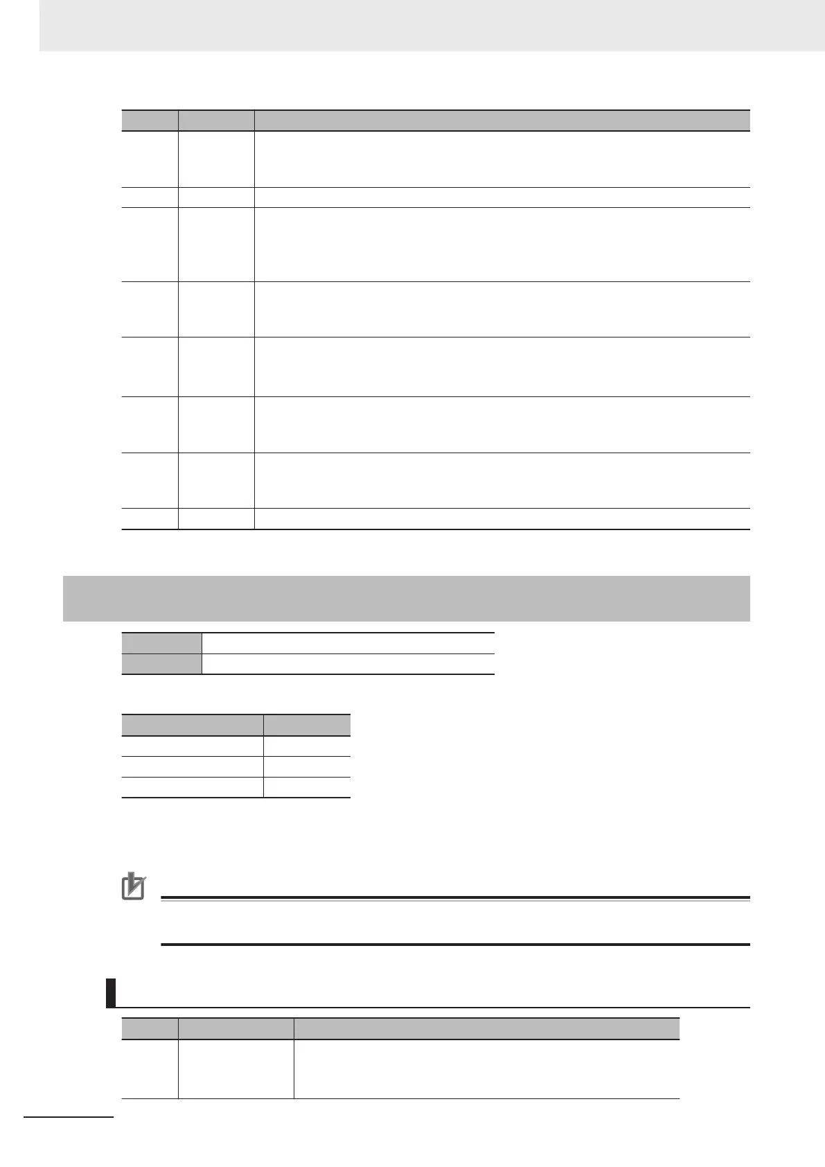
Bit Name Function
19 TxEnable SL2-100 data send enable
0: SL2-100 output stop
1: SL2-100 output enable
18 Reserve Always set 0.
17 ClockSel Set the clock to use for the linear interpolation of SL2-100 and the delay time of PWM
output.
0: Servo clock
1: Phase clock
16 Sync Set the synchronous or asynchronous mode for linear interpolation.
0: Asynchronous mode
1: Synchronous mode
15 to 13 Control Bits
Set the type of transmission data.
*1
001: Command position
1
1
1: Control command
12 EdgeSel Set the clock edge to use for linear interpolation.
0: Falling edge
1: Rising edge
11 Tx Valid Enable or disable transmission data.
0: Transmission data disable
1: T
ransmission data enable
10 to 0 Reserve Always set 0.
*1. Always set 001 or 111.
A-9-2
Gate3[i].Chan[j].DAC[0] (Setting of Command Position and Con-
trol Command)
Description Setting of command position and control command
Default 0
Depending on the channel, this setting varies as follows.
Register Description
Gate3[i].Chan[0].Dac[0] X-axis setting
Gate3[i].Chan[1].Dac[0] Y-axis setting
Gate3[i].Chan[2].Dac[0] Z-axis setting
Note
Gate3[i].Chan[3].Dac[0] is not used.
The setting of this register depends on XY2-100 and SL2-100.
Precautions for Correct Use
This register does not support hexadecimal notation such as $00000000 to $FFFFFFFF. Use
decimal notation for setting.
For CK3W-GC1£00 Units (XY2-100)
Bit Name Function
31 to 08 Command position Write a command position in the CK3W-GC Unit from the CPU Unit.
Data format of the command position is determined by ModeSel.
The setting range is from -2
23
to 2
23
.
Appendices
A-34
CK3M-series Programmable Multi-Axis Controller User's Manual Hardware (O036)

 Loading...


