Type Pin No. Cable color
Tag
*1
Signal
XY2-100 SL2-100
XY Z XY Z
Pair 1 13 Blue 13 GND GND Not wired Not wired
14 White 14 GND GND Not wired Not wired
Pair 2 1 Yellow 1 CHX+ CHZ+ XY-IN+ Z-IN+
6 White 6 CHX- CHZ- XY-IN- Z-IN-
Pair 3 2 Green 2 CHY+ Not wired XY-OUT+ Z-OUT+
7 White 7 CHY- Not wired XY-OUT- Z-OUT-
Pair 4 3 Red 3 XY-SYNC+ Z-SYNC+ Not wired Not wired
8 White 8 XY-SYNC- Z-SYNC- Not wired Not wired
Pair 5 4 Purple 4 XY-CLOCK+ Z-CLOCK+ Not wired Not wired
9 White 9 XY-CLOCK- Z-CLOCK- Not wired Not wired
Pair 6 5 Blue 5 XY-STATUS+ Z-STATUS+ Not wired Not wired
10 Brown 10 XY-STATUS- Z-STATUS- Not wired Not wired
*1. For the purpose of identification, each line has the tag that shows a pin No.
Note
The cable shield is connected to the connector shell of the encoder connector.
Additional Information
You may use a self-made cable.
When you create a self-made cable, use a shielded twisted-pair cable to block the ef
fects of
noise.
5-7-2
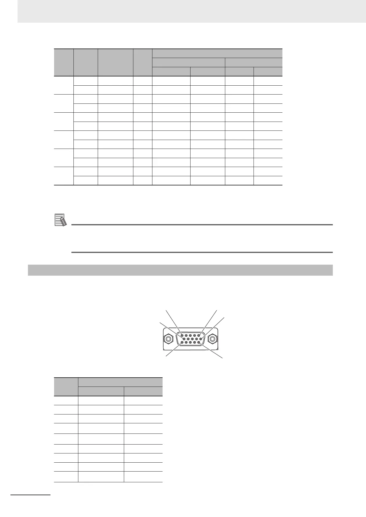
Laser Connector Wiring
The Unit side connector is a high-density D-sub 15-pin female connector (MIL-C-24308 compliant,
lock screw #4-40 UNC).
Pin No.
XY
Signal Input/Output
1 NC -
2 NC -
3 NC -
4
OUT0
*1
Output
5
OUT1
*1
*2
Output
6 NC -
7 NC -
8 NC -
9
OUT_COM0
*1
Output
5 Wiring
5-48
CK3M-series Programmable Multi-Axis Controller User's Manual Hardware (O036)

 Loading...


