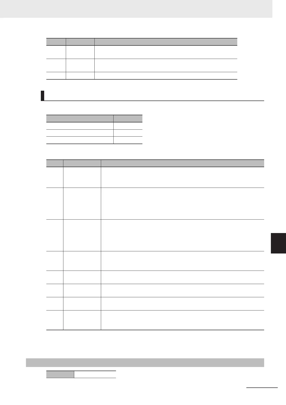
Bit Name Function
31 to 13 Status Stores the status data sent from the Galvo Scanner.
For details on the status data, refer to the manual for the Galvo Scanner.
12
Status Parity Stores the parity bits added to the status data.
Use a user program to check that the parity is correct.
11 to 00 Reserve Always set 0.
For CK3W-GC2£00 Units (SL2-100)
Depending on the channel, this setting varies as follows.
Register Description
Gate3[i].Chan[0].SerialEncDataB X-axis status
Gate3[i].Chan[1].SerialEncDataB Y-axis status
Gate3[i].Chan[2].SerialEncDataB Z-axis status
Note
Gate3[i].Chan[3].SerialEncDataB is not used.
Bit Name Function
31 TxRx_Error Detects an error in communications with the Galvo Scanner.
0: Communications normal
1: Communications abnormal
*1
30 Power_OK Shows the status of the internal power supply voltage of the Galvo Scanner.
0: Internal power supply voltage abnormal in the Galvo Scanner
1: Internal power supply voltage normal in the Galvo Scanner
If any internal power supply voltage error is found, follow the manual for the Galvo
Scanner to remove it.
29 Temp_OK Shows the status of the internal temperature of the Galvo Scanner.
0: Internal temperature abnormal in the Galvo Scanner
1: Internal temperature normal in the Galvo Scanner
If any internal temperature error is found, follow the manual for the Galvo Scanner
to remove it.
28 Position_Ack Shows that the Galvo Scanner received position data.
0: The Galvo Scanner did not receive position data.
1: The Galvo Scanner received position data.
27 Data for mainte-
nance
Used for maintenance.
26 to
14
Reserve Always set 0.
13 to
8
Data for mainte-
nance
Used for maintenance.
7 to 0 Number of
frames received
Counts the number of frames received by the CK3W-GC Unit.
Since a frame comes every 10 µs, you can confirm that the reception data is com-
ing when you check that this data is counting up.
*1. Depending on the timing of starting communications with the Galvo Scanner, TxRx_Error may turn ON in
the detection of the first frame.
Do not use a user program to check the error that may occur at the start of communications.
A-9-6
Gate3[i].Chan[0].CompA (PWM Output Setting)
Description PWM output setting
Appendices
A-37
CK3M-series Programmable Multi-Axis Controller User's Manual Hardware (O036)
A-9 Software Reference of Laser Interface Unit
A
A-9-6 Gate3[i].Chan[0].CompA (PWM Output Setting)

 Loading...


