A-9
Software Reference of Laser Interface
Unit
This section describes register settings of the Laser Interface Unit.
These register settings are different from the definitions descried in the Power PMAC Software
Reference Manual (Cat. No. O015).
A-9-1
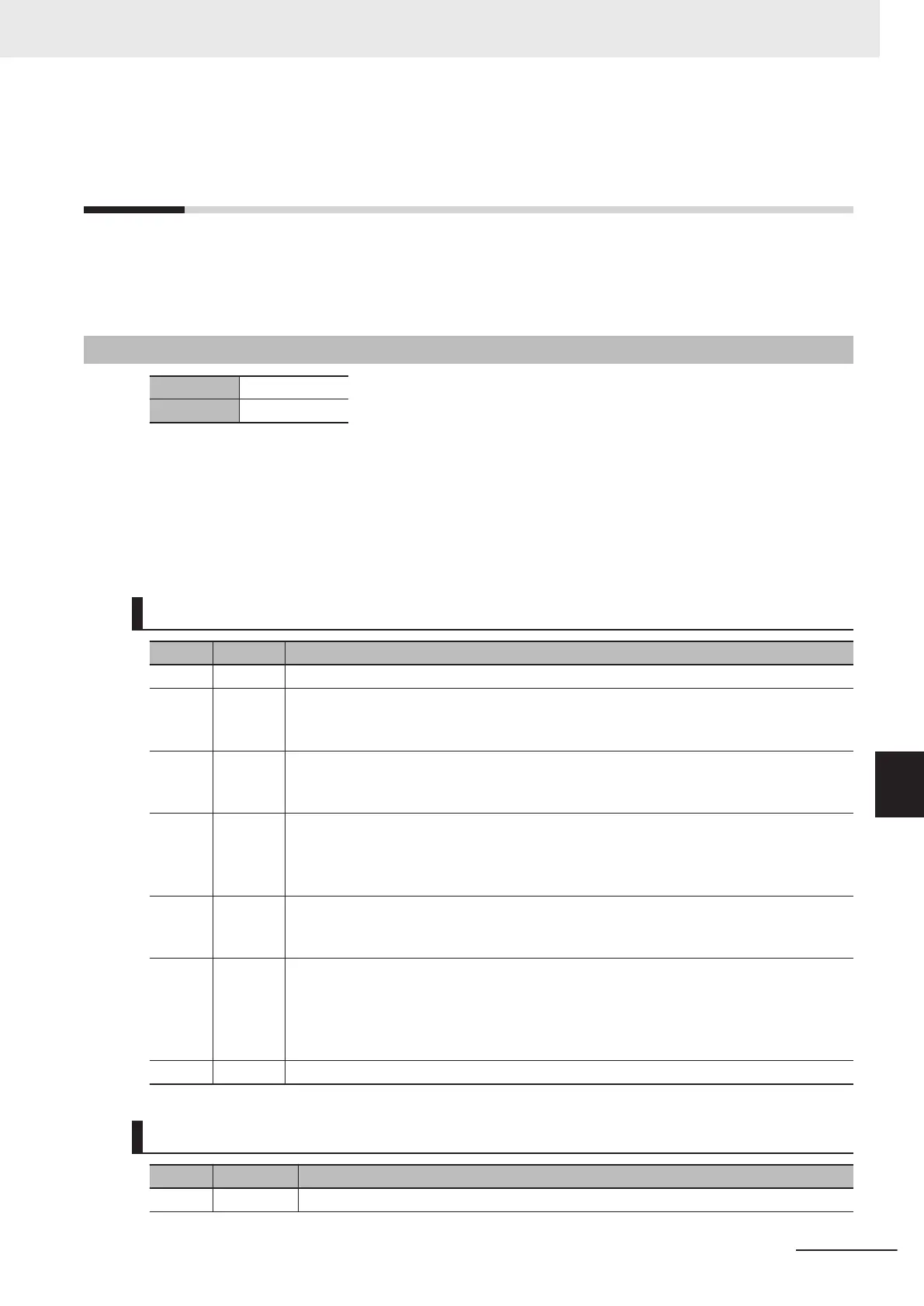
Gate3[i].SerialEncCtrl (Control Register)
Description Control register
Default $00000000
This register is write-protected, so you cannot change it unless you write a key value in
Gate3[i].WpKey.
Y
ou can reset the write protection automatically in the script environment by writing the key value in
Sys.WpKey.
The setting of this register depends on XY2-100 and SL2-100.
For CK3W-GC1£00 Units (XY2-100)
Bit Name Function
31 to 20 Reserve Always set 0.
19 TxEnable XY2-100 data send enable
0: XY2-100 output stop
1: XY2-100 output enable
18 Parity Set the send parity.
0: Even parity
1: Odd parity
17 ClockSel Set the clock to use for the linear interpolation of XY2-100 and the delay time of PWM
output.
0: Servo clock
1: Phase clock
16 Sync Set the synchronous or asynchronous mode for linear interpolation.
0: Asynchronous mode
1: Synchronous mode
15 to 14 ModeSel Select a data format of the position command.
00: 16-bit data format
01: 18-bit data format
10: 20-bit data format
1
1: Setting prohibited
13 to 0
Reserve Always set 0.
For CK3W-GC2£00 Units (SL2-100)
Bit Name Function
31 to 20 Reserve Always set 0.
Appendices
A-33
CK3M-series Programmable Multi-Axis Controller User's Manual Hardware (O036)
A-9 Software Reference of Laser Interface Unit
A
A-9-1 Gate3[i].SerialEncCtrl (Control Register)

 Loading...


