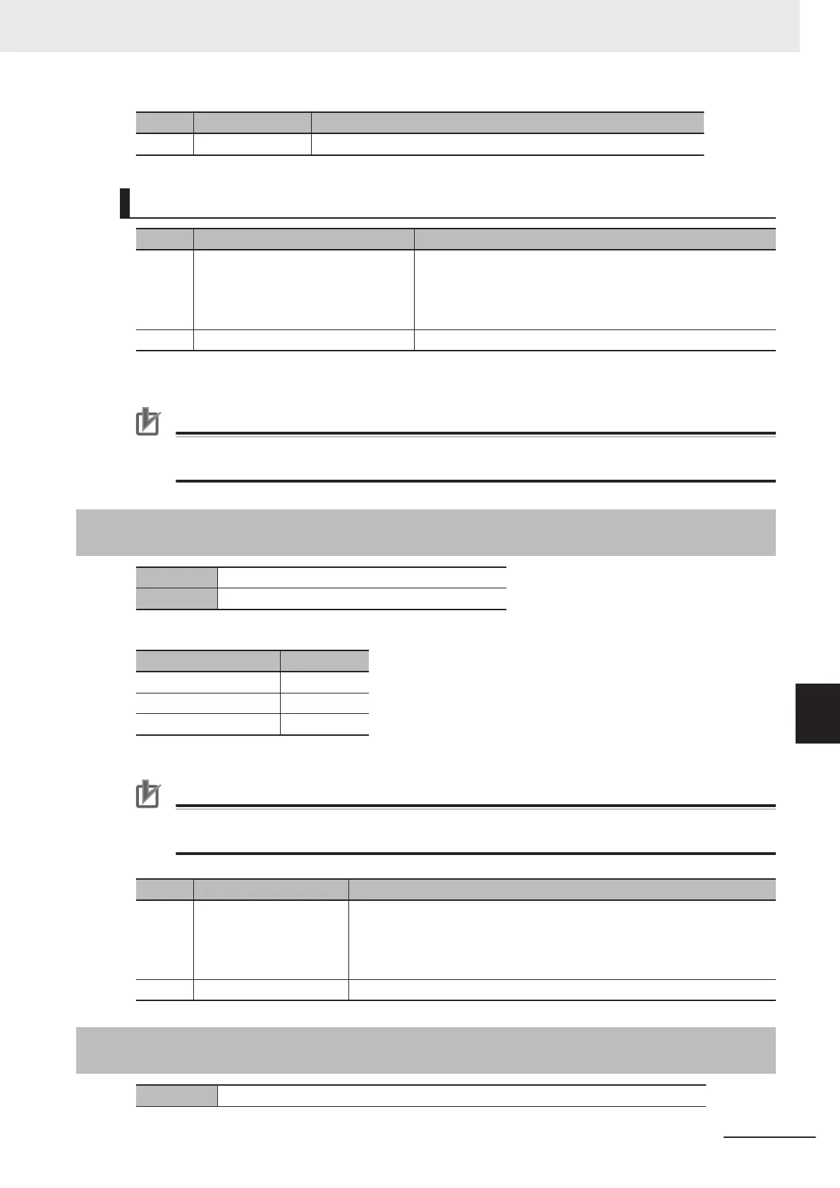
Bit Name Function
07 to 00 Reserve Always set 0.
For CK3W-GC2£00 Units (SL2-100)
Bit Name Function
31 to 08 Command position or control com-
mand
*1
This data depends on the setting of Control Bit as follows.
• Control Bit = 001: Command position
• Control Bit = 11
1: Control command
The setting range of command position is from -2
23
-1 to 2
23
-1.
07 to 00 Reserve Always set 0.
*1. For details on the Command position and the control command, refer to 3-7-7 SL2-100 Interface
on page
3-76.
Precautions for Correct Use
Since this register cannot use hexadecimal numbers, use decimal numbers even when you set
control commands.
A-9-3
Gate3[i].Chan[j].DAC[1] (Setting of Command Position Compen-
sation Value)
Description Setting of command position compensation value
Default 0
Depending on the channel, this setting varies as follows.
Register Description
Gate3[i].Chan[0].Dac[1] X-axis setting
Gate3[i].Chan[1].Dac[1] Y-axis setting
Gate3[i].Chan[2].Dac[1] Z-axis setting
Note
Gate3[i].Chan[3].Dac[1] is not used.
Precautions for Correct Use
This register does not support hexadecimal notation such as $00000000 to $FFFFFFFF. Use
decimal notation for setting.
Bit Name Function
31 to 08 Command position com-
pensation value
Write a command position compensation value in the CK3W-GC Unit
from the CPU Unit.
Data format is determined by ModeSel.
The setting range is from -2
23
-1 to 2
23
-1.
07 to 00 Reserve Always set 0.
A-9-4
Gate3[i].Chan[j].SerialEncDataA (Command Position after Inter-
polation, Reception Data)
Description Command position after interpolation, and reception data based on control command
Appendices
A-35
CK3M-series Programmable Multi-Axis Controller User's Manual Hardware (O036)
A-9 Software Reference of Laser Interface Unit
A
A-9-3 Gate3[i].Chan[j].DAC[1] (Setting of Command Position Compensa-
tion Value)

 Loading...


