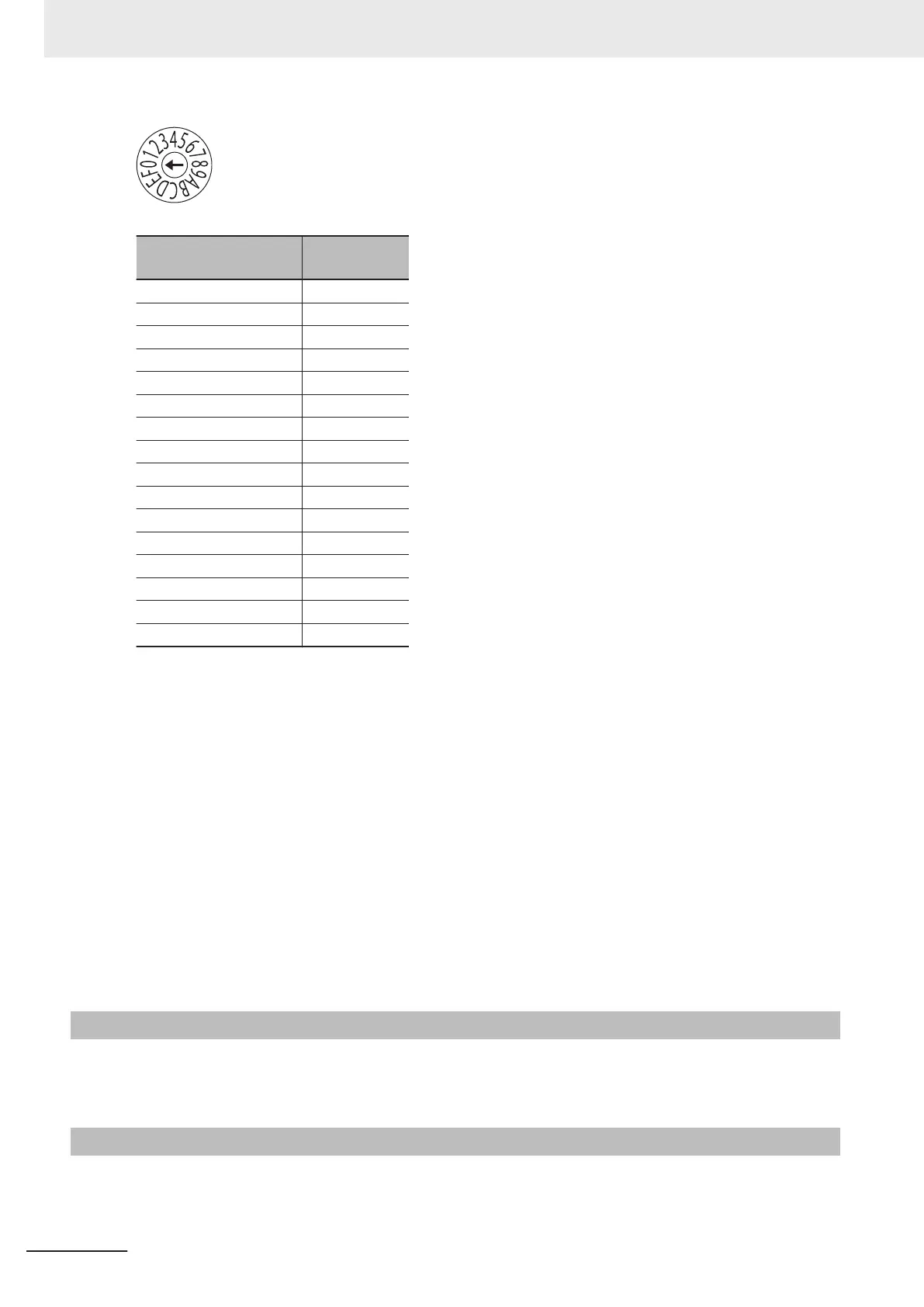
Address switch setting
Power PMAC
“Gate3” Index
0 0
1 1
2 2
3 3
4 4
5 5
6 6
7 7
8 8
9 9
A 10
B 11
C 12
D 13
E 14
F 15
For example, if the address switch setting is 0, the Gate3 Index becomes 0.
In this case, this Unit is accessed with a Gate3[0] data structure.
Make sure that the address switch settings of Units do not overlap.
If they overlap, the Sys.Status register CK3WConfigErr becomes 7.
Refer to 6-4 Sys.Status Register on page 6-10 for Sys.Status.
One CK3W Unit in the system supplies servo clock and phase clock signals to all the other Units.
The supply-source CK3W Unit must be installed to the CPU Rack.
Connect the Unit with the smallest address value to the CPU Rack because, by default, it is the supply
source of clock signals.
Y
ou may specify the Unit with a desired address as the clock supply source by setting the register.
If the Unit that serves as the clock supply source is connected to the Expansion Rack, an error occurs
because the CPU Unit cannot recognize clock signals.
If this error occurs, the Sys.Status register Sys.NoClocks becomes 1.
3-6-5
Terminal Arrangement
For the connector arrangement of the encoder connector, refer to 5-6-1 Encoder Connector W
iring on
page 5-44.
3-6-6
Software Settings
Use the following register settings for the software settings of the Encoder Input Unit.
3 Configuration Units
3-64
CK3M-series Programmable Multi-Axis Controller User's Manual Hardware (O036)

 Loading...


