5-6
Encoder Input Unit
This section describes the wiring for the Serial Encoder Input Unit.
5-6-1
Encoder Connector Wiring
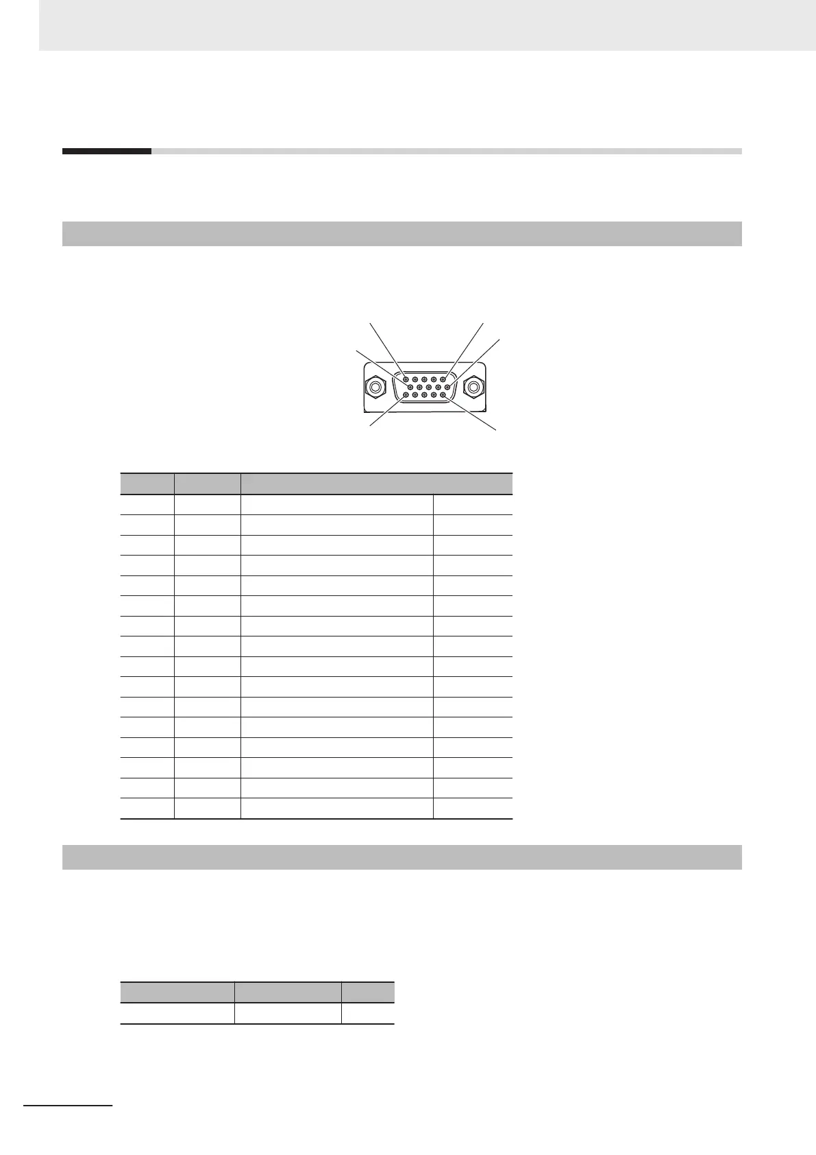
The Unit side connector is a high-density D-sub 15-pin female connector (MIL-C-24308 compliant,
lock screw #4-40 UNC).
Pin No. Symbol Serial Encoder
1 NC Not wired -
2 NC Not wired -
3 NC Not wired -
4 CLK+ Serial Encoder CLK+ Output
5 DATA+ Serial Encoder DAT+ Input/Output
6 NC Not wired -
7 NC Not wired -
8 NC Not wired -
9 CLK- Serial Encoder CLK- Output
10 DATA- Serial Encoder DAT- Input/Output
11 ENCPWR Encoder Power Supply (+5 VDC) Output
12 ENCPWR Encoder Power Supply (+5 VDC) Output
13 GND Encoder Power Supply (GND) Output
14 GND Encoder Power Supply (GND) Output
15 NC Not wired -
Shell SHELL Shield
5-6-2
Dedicated Cable
The dedicated cables for wiring to the encoder connector are provided as an option.
The encoder connection side has discrete wires.
Perform wiring to match the encoder specifications.
The cable model is as shown below.
Type Model Length
For Serial Encoder CK3W-CAES03A 3 m
5 Wiring
5-44
CK3M-series Programmable Multi-Axis Controller User's Manual Hardware (O036)

 Loading...


