Data Format of Command Position
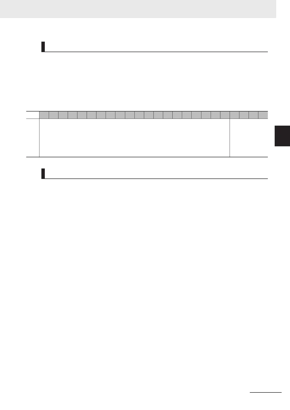
A command position is 24-bit data.
To set the command position, use Gate3[i].Chan[j].DAC[0] [31:08] when Control Bit (Gate3[i].Serial-
EncCtrl [15:13]) is 001.
Data format is as follows.
The data range is from -2
23
to 2
23
.
Data to be sent to the Galvo Scanner is limited to the command position (integer part).
The command position (fractional part) is used to improve the accuracy of linear interpolation.
23 22 21 20 19 18 17 16 15 14 13 12 11 10 9 8 7 6 5 4 3 2 1 0
Co
mm
and
po-
si-
tion
Command position (integer part) 20 bits Command posi-
tion (fractional
part) 4 bits
Linear Interpolation of Command Position
The SL2-100 Interface sends data every 10 µs.
However, since the CPU Unit writes a command position in the CK3W-GC Unit in synchronization with
a phase or a servo clock, generally the command position data from the CPU Unit can only be refresh-
ed in a cycle longer than 10 µs.
For this reason, the command position from CPU is applied linear interpolation and it is sent to the
Galvo Scanner as the data of SL2-100.
For the clock that determines an interpolation cycle, you can select a servo clock or a phase clock by
setting ClockSel (Gate3[i].SerialEncCtrl [17]).
The ClockSel setting should be the same as a setting of the clock that controls the motor of PMAC (bit
3 of Motor[x].PhaseCtrl).
Additionally, you can select rising edge or falling edge by setting EdgeSel (Gate3[i].SerialEncCtrl [12]).
A command position is applied linear interpolation in synchronous mode or asynchronous mode.
You can select synchronous mode or asynchronous mode by setting Sync (Gate3[i].SerialEncCtrl
[16]).
Operation in Synchronous Mode
In this mode ensure that the interpolation clock (Phase or Servo) period is set to an integer multiple
of 10 µs.
The CK3W-GC Unit captures a command position at the falling edge (rising edge) of an interpola-
tion clock, and sends that command position in an SL2-100 transmission cycle at the falling edge
(rising edge) of the next interpolation clock.
As the SL2-100 data between interpolation clocks, the value calculated by linear interpolation is
sent.
Y
ou can match the command position from the CPU Unit with the shape of SL2-100 data by using
this mode.
3 Configuration Units
3-77
CK3M-series Programmable Multi-Axis Controller User's Manual Hardware (O036)
3-7 Laser Interface Unit
3
3-7-7 SL2-100 Interface

 Loading...


