Type Pin No. Cable color Mark Signal
Pair 5 15 Gray Black OutFlagB
14 Gray Red GND
*1.
In order to make a connection with the OMRON G5-series Servo Drive R88D-KT£££, Pin 1 and Pin 5,
and Pin 6 and Pin 10 are short-circuited inside the connector
.
Y
ou can also connect a normal digital quadrature encoder which does not use serial encoder DAT by
disabling the serial encoder. To disable the serial encoder, set Gate3[i].Chan[j].SerialEncEna=0.
Note
The cable shield is connected to the connector shell of the encoder connector.
When using this cable, set to OutFlagD = 1 to disable the serial encoder DAT terminating resistance.
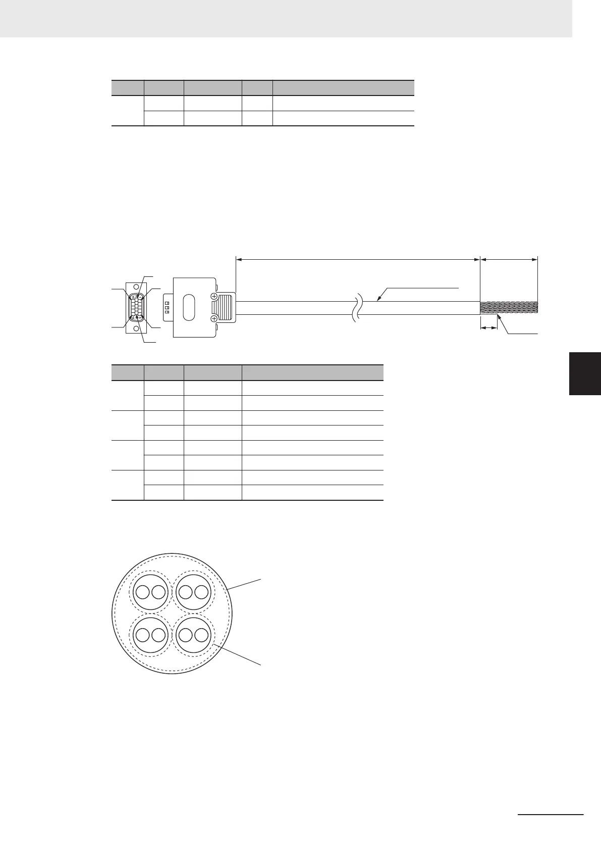
For Sinusoidal Encoder
Shield
1
0
3,000 35
24AWG x 4 Pairs
6
1
5
10
15
11
Type Pin No. Cable color Signal
Pair 1 11 Black Encoder Power Supply (+5 VDC)
13 Blue Encoder Power Supply (GND)
Pair 2 1 Black SIN+
6 Red SIN-
Pair 3 2 Black COS+
7 White COS-
Pair 4 3 Black INDEX+
8 Green INDEX-
Note
The cable shield consists of an overall shield and pair shields.
The overall shield is connected to the connector shell of the encoder connector.
The pair shields are connected to the Encoder Power Supply (GND) pin.
Overall shield
Pair shield
5 Wiring
5-21
CK3M-series Programmable Multi-Axis Controller User's Manual Hardware (O036)
5-3 Axis Interface Unit Wiring
5
5-3-1 Encoder Connector Wiring

 Loading...


