Type Pin No. Cable color Mark
Signal
U, V, W Serial Encoder
Pair 2 4 Pink Black Hall sensor U Serial Encoder CLK+
9 Pink Red Hall sensor V Serial Encoder CLK-
Pair 3 5 Green Black Hall sensor W Serial Encoder DAT+
10 Green Red Hall sensor T Serial Encoder DAT-
Note
The cable shield is connected to the connector shell of the encoder connector.
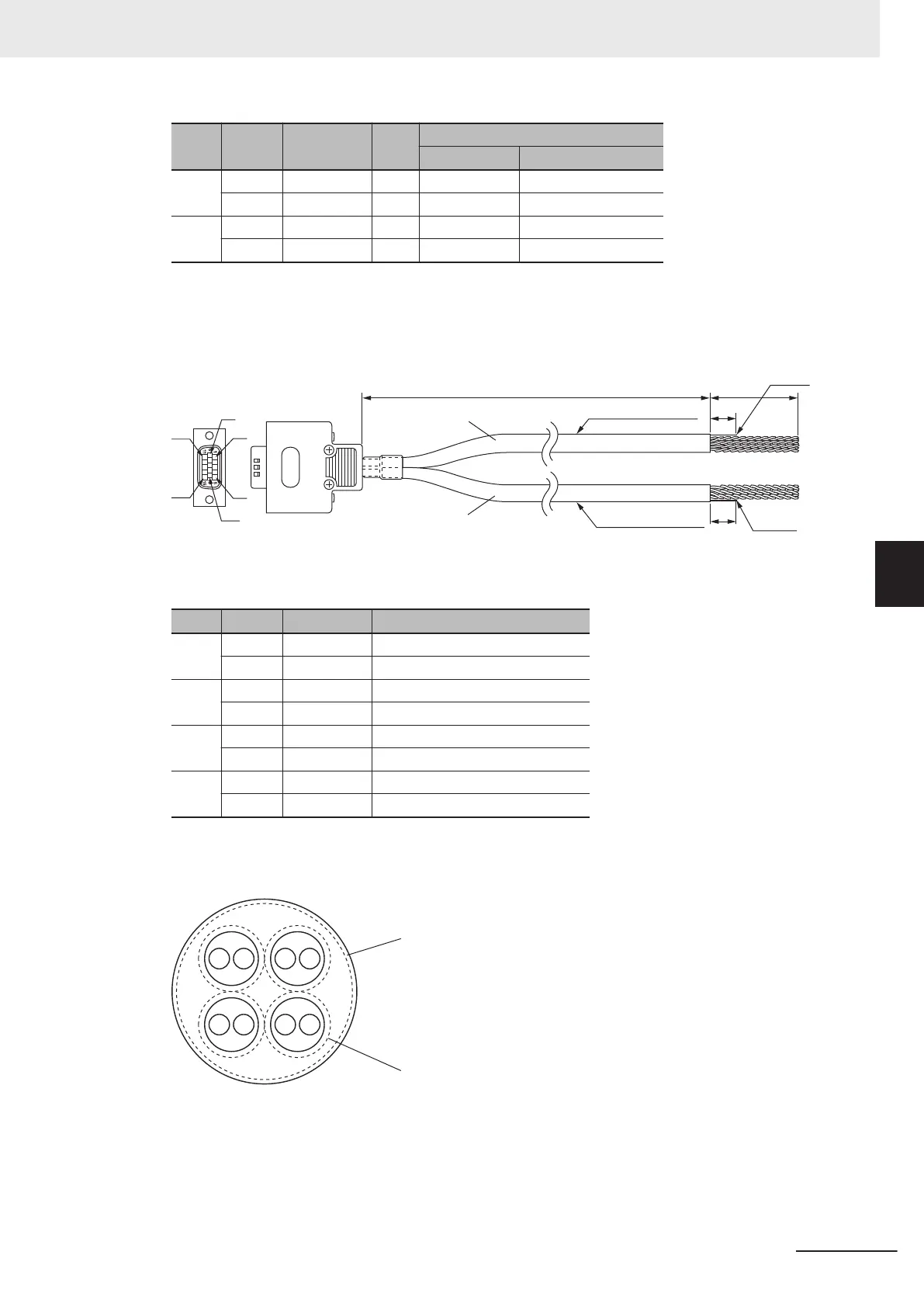
For “Sinusoidal Encoder + UVW Signal” or “Sinusoidal Encoder + Serial
Encoder”
Shield
Shield
Cable 1
Cable 2
3,000
35
10
10
24AWG × 4 Pairs
24AWG × 3 Pairs
6
1
5
10
15
11
Cable 1
Type Pin No. Cable color Signal
Pair 1 11 Black Encoder Power Supply (+5 VDC)
13 Blue Encoder Power Supply (GND)
Pair 2 1 Black SIN+
6 Red SIN-
Pair 3 2 Black COS+
7 White COS-
Pair 4 3 Black INDEX+
8 Green INDEX-
Note
The cable shield consists of an overall shield and pair shields.
The overall shield is connected to the connector shell of the encoder connector.
The pair shields are connected to the Encoder Power Supply (GND) pin.
Overall shield
Pair shield
Cable 2
5 Wiring
5-23
CK3M-series Programmable Multi-Axis Controller User's Manual Hardware (O036)
5-3 Axis Interface Unit Wiring
5
5-3-1 Encoder Connector Wiring

 Loading...


