SER_Clock (MHz)=
(M+1)
×2
N
100
M = SerialClockMDiv
N = SerialClockNDiv
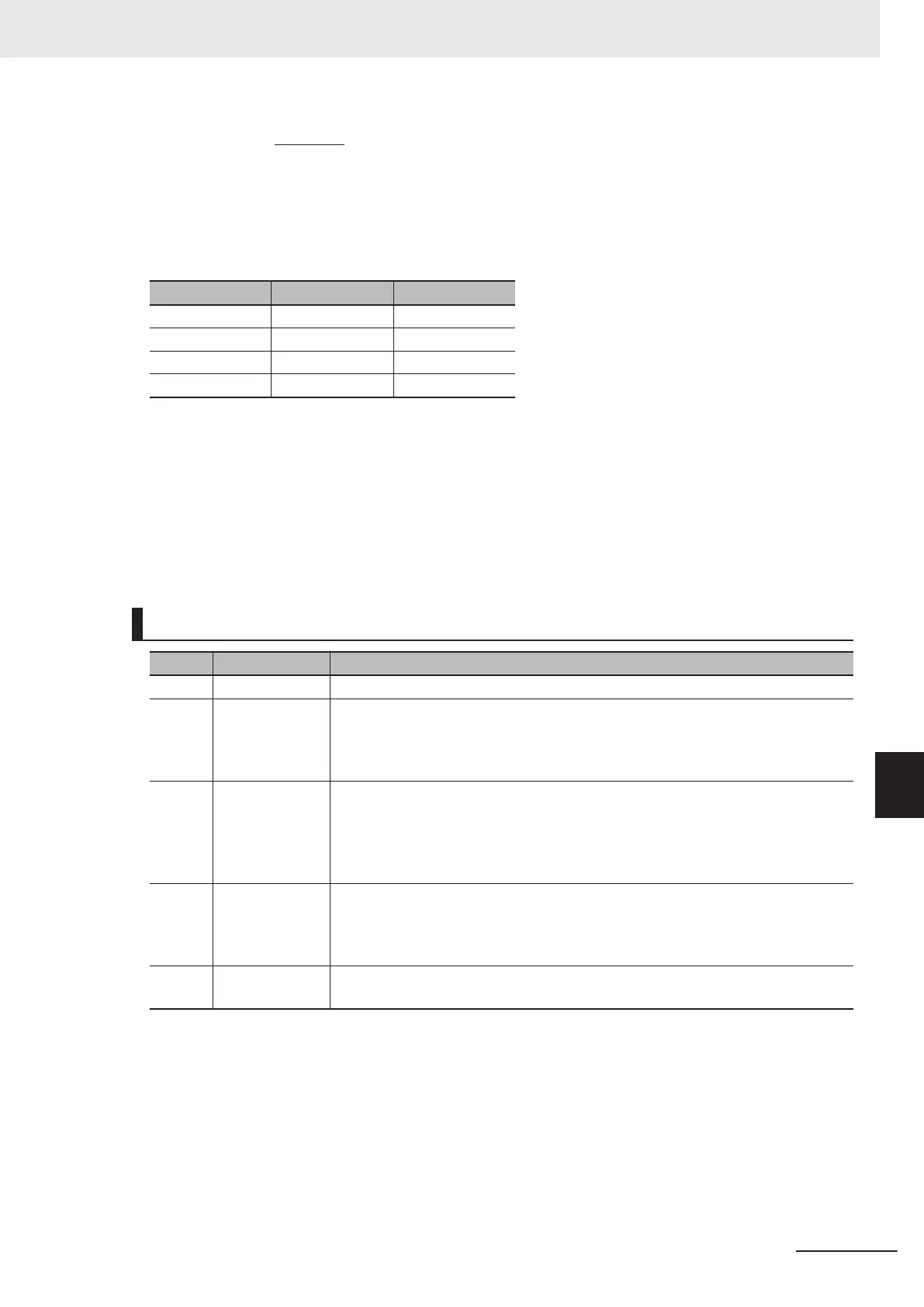
The following shows examples of the clock frequency settings to be used in Endat2.2.
Clock frequency SerialClockMDiv SerialClockNDiv
2 MHz 1 ($01) 0
1 MHz 3 ($03) 0
500 kHz 7 ($07) 0
100 kHz 39 ($27) 0
The following shows examples of general settings.
SerialClockMDiv: = $01 // Serial clock frequency = 2 MHz
SerialClockNDiv: = 0 // Serial clock frequency = 2 MHz
SerialTrigClockSel: = 0 // Phase clock cycle used
SerialTrigEdgeSel: = 0 // Rising edge used
SerialTrigDelay: = 0 // Delay set to 0
SerialProtocol: = $03 // Endat2.2 selected
For R88M-1L£/-1M£ Motor Built-in Encoder
Bit Name Function
31 to 18 Reserve Always set 0.
17 SerialTrigClock-
Sel
Selection of a serial trigger clock
Set which clock to do encoder reading on, phase or servo.
0: Phase clock
1: Servo clock
16 SerialTrigEdge-
Sel
Selection of a serial trigger clock edge
SetSet which edge to start encoder reading at, the rising edge or falling edge of
the clock.
0: Rising edge
1: Falling edge
15 to 08 SerialTrigDelay Setting of a delay from the serial trigger clock edge
Set the delay time between clock edge and encoder reading. The unit is an inter-
mediate clock (SER_Clock) cycle.
The setting range is from 0 to 255.
07 to 00 SerialProtocol Serial encoder protocol setting
Set $0E for R88M-1L£/-1M£ Motor built-in encoder
.
For R88M-1L£/-1M£ Motor built-in encoder, you do not need to set clock frequency
.
The following shows examples of general settings.
SerialTrigClockSel: = 0 // Phase clock cycle used
SerialTrigEdgeSel: = 0 // Rising edge used
SerialTrigDelay: = 0 // Delay set to 0
SerialProtocol: = $0E // R88M-1L/-1M Motor built-in encoder selected
Appendices
A-23
CK3M-series Programmable Multi-Axis Controller User's Manual Hardware (O036)
A-8 Software Reference of Encoder Input Unit
A
A-8-1 Gate3[i].SerialEncCtrl (Serial Encoder Control)

 Loading...


