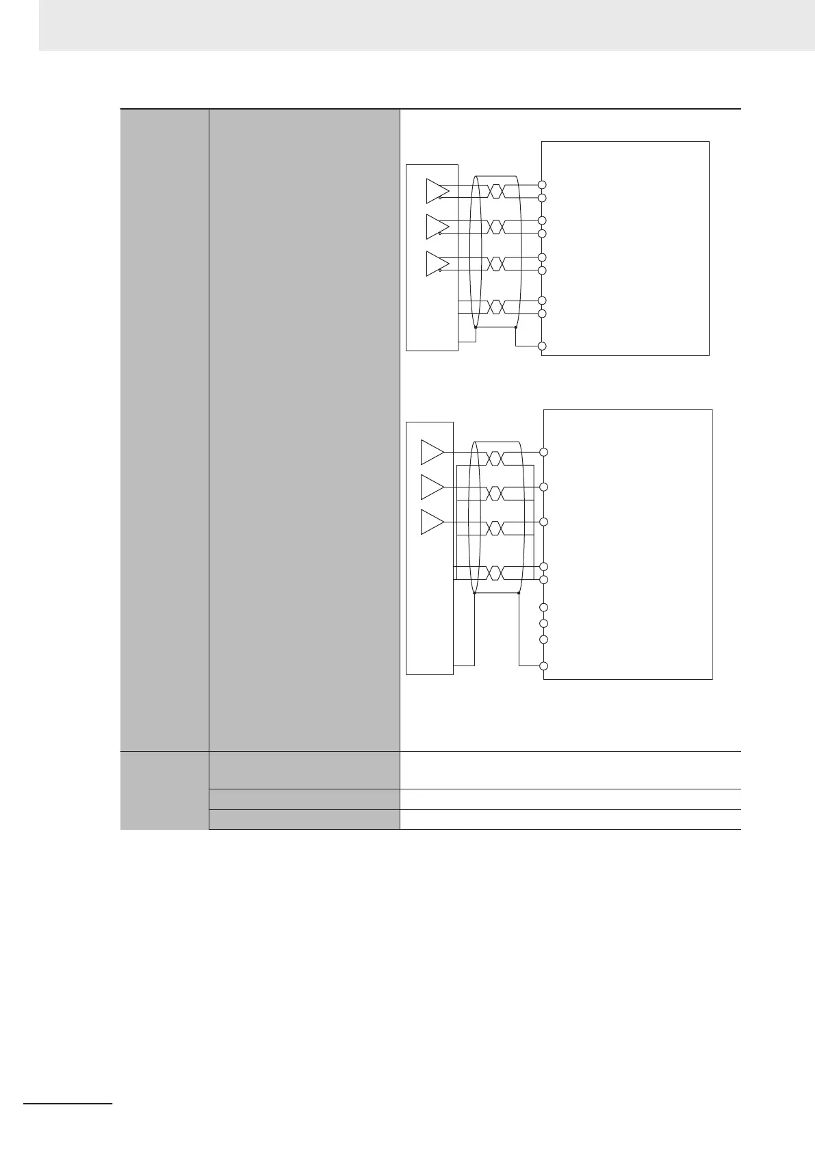
Terminal connection diagram With differential input
Encoder
Encoder A+
Encoder A-
Encoder B+
Encoder B-
Encoder C+
Encoder C-
Encoder power supply
(+5 VDC)
Encoder power supply
(GND)
Connector shell
+5 V
0V
+
-
+
-
+
-
With single-ended input
Encoder
Encoder A+
Encoder A-
Encoder B-
Encoder C-
Encoder B+
Encoder C+
(+5 VDC)
Encoder power supply
Encoder power supply
(GND)
Connector shell
+5 V
0 V
With single-ended input, use twisted-pair wire to improve
noise resistance, and pair the respective signals of encoder
A+, B+, C+ with GND.
Serial encod-
er input
Supported protocol Contact your OMRON representative for information on the
support protocols.
Clock output EIA standard RS-422A line driver levels
Data I/O EIA standard RS-485 line driver/receiver level
3 Configuration Units
3-18
CK3M-series Programmable Multi-Axis Controller User's Manual Hardware (O036)

 Loading...


