93
Wiring Section 3-4
3-4 Wiring
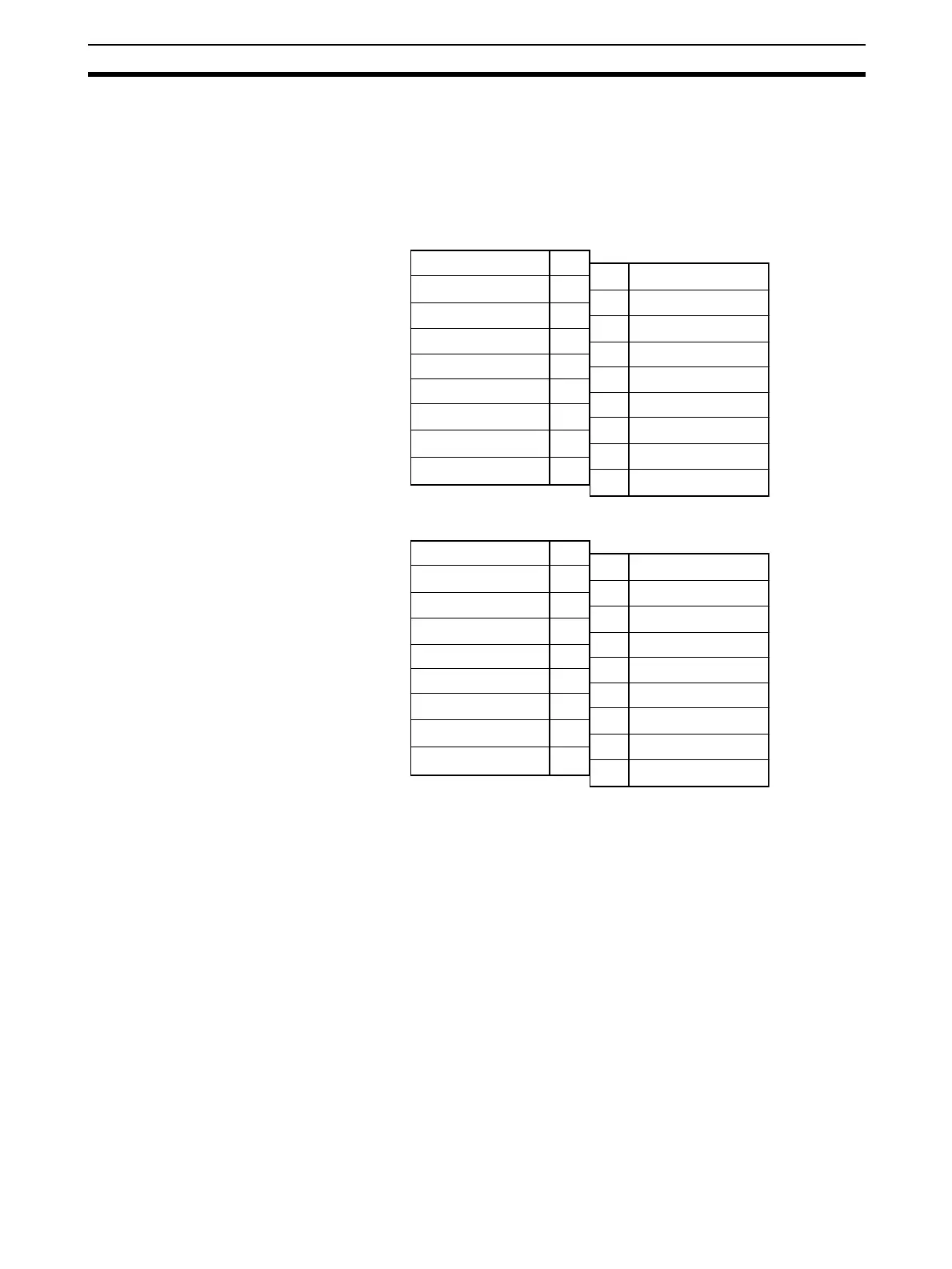
3-4-1 Terminal Arrangement
The signal names corresponding to the connecting terminals are as shown in
the following diagram.
CJ1W-AD041-V1
CJ1W-AD081-V1
Note 1. The analog input numbers that can be used are set in the Data Memory
(DM).
2. The input signal ranges for individual inputs are set in the Data Memory
(DM). They can be set in units of input numbers.
3. The AG terminals are connected to the 0-V analog circuit in the Unit. Con-
necting shielded input lines can improve noise resistance.
!Caution Do not make any connections to the N.C. terminals.
Input 2 (+)
Input 2 (–)
Input 4 (+)
Input 4 (–)
AG
N.C.
N.C.
N.C.
N.C.
Input 1 (+)
Input 1 (–)
Input 3 (+)
Input 3 (–)
AG
N.C.
N.C.
N.C.
N.C.
B1
B2
B3
B4
B5
B6
B7
B8
B9
A1
A2
A3
A4
A5
A6
A7
A8
A9
Input 2 (+)
Input 2 (–)
Input 4 (+)
Input 4 (–)
AG
Input 6 (+)
Input 6 (–)
Input 8 (+)
Input 8 (–)
Input 1 (+)
Input 1 (–)
Input 3 (+)
Input 3 (–)
AG
Input 5 (+)
Input 5 (–)
Input 7 (+)
Input 7 (–)
B1
B2
B3
B4
B5
B6
B7
B8
B9
A1
A2
A3
A4
A5
A6
A7
A8
A9
 Loading...


