33
Wiring Section 2-4
CS1W-AD161
Note 1. The analog input numbers that can be used are set in the Data Memory
(DM).
2. The input signal ranges for individual inputs are set in the Data Memory
(DM). They can be set in units of input numbers.
3. The AG terminals (A8, B8) are connected to the 0-V analog circuit in the
Unit. Connecting shielded input lines can improve noise resistance.
!Caution Do not make any connections to the N.C. terminals.
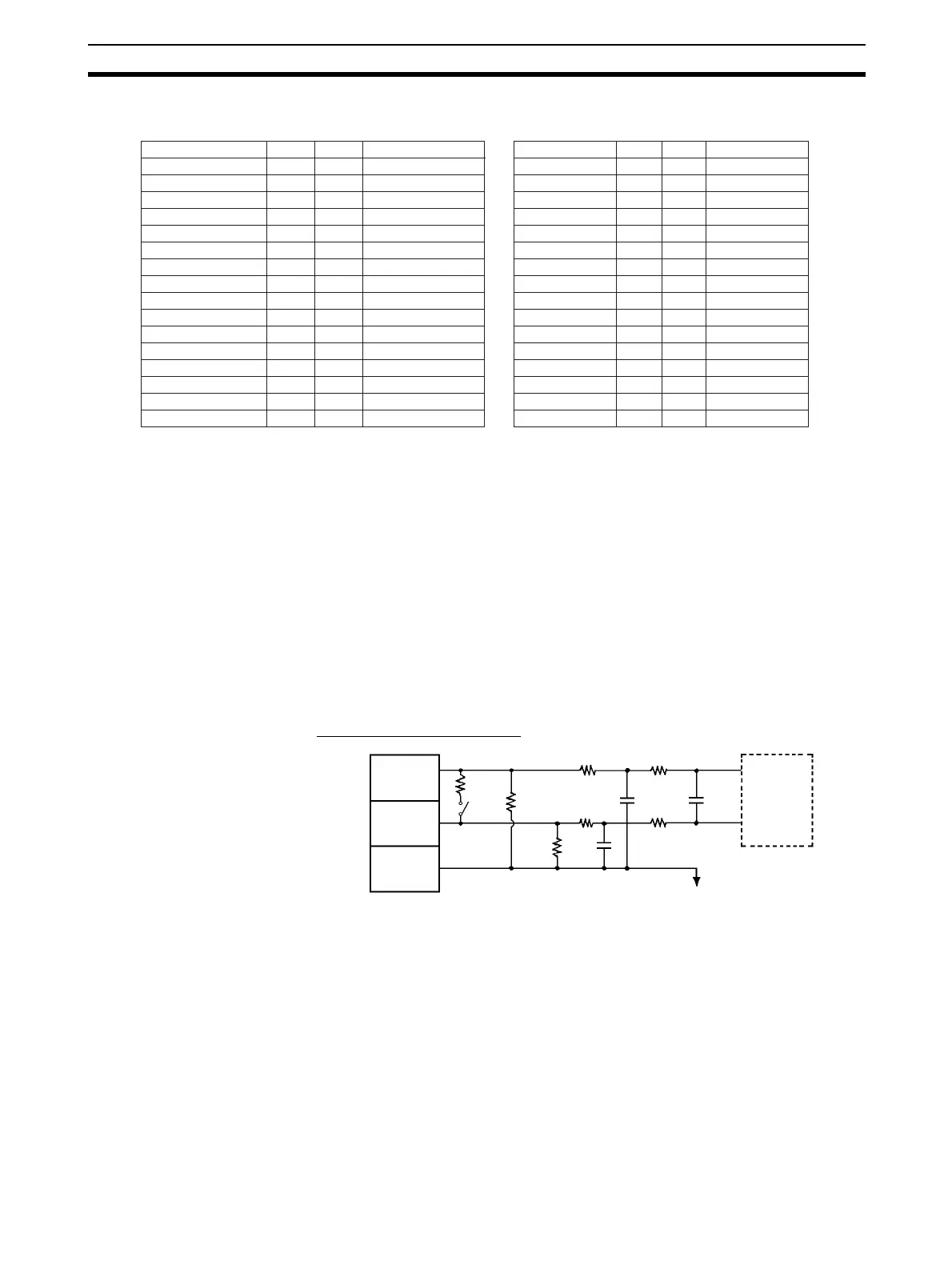
2-4-2 Internal Circuitry
The following diagrams show the internal circuitry of the analog input section.
Input Circuitry
CS1W-AD041-V1/AD081-V1
CN2 Inputs 9 to16 CN1 Inputs 1 to 8
Input 9+ 1 2 Input 10+ Input 1+ 1 2 Input 2+
Current mode 9 3 4 Current mode 10 Current mode 1 3 4 Current mode 2
Input 9− 5 6 Input 10− Input 1− 5 6 Input 2−
AG 7 8 AG AG 7 8 AG
Input 11+ 9 10 Input 12+ Input 3+ 9 10 Input 4+
Current mode 11 11 12 Current mode 12 Current mode 3
11
12 Current mode 4
Input 11− 13 14 Input 12− Input 3− 13 14 Input 4−
AG AG AG 15 16 AG
Input 13+ 17 18 Input 14+ Input 15+ 17 18 Input 6+
Current mode 13 19 20 Current mode 14 Current mode 5 19 20 Current mode 6
Input 13− 21
22
Input 14− Input 5− 21 22 Input 6−
AG AG AG 23 24 AG
Input 15+ Input 16+ Input 7+ 25 26 Input 8+
Current mode 15 28 Current mode 16 Current mode 7 27 28 Current mode 8
Input 15− 30 Input 16− Input 7− 29 30 Input 8−
AG 31 32 AG AG 31 32 AG
NC 33 NC NC 33 34 NC
34
15
16
23
24
25
26
27
29
1 M
15 k 15 k
15 k 15 k
AG (common to all inputs)
Input (+)
Input (–)
AG
(analog
0 V)
Input circuit
and
conversion
circuit
1 M
Voltage/
current
input switch
250
 Loading...


