174
Operating Procedure Section 5-2
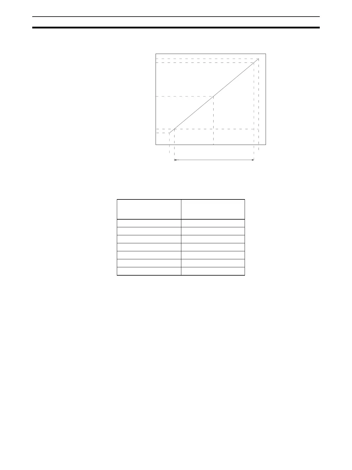
Range: −10 to 10 V
Note The set values for a range of –10 to 10 V will be as follows:
5-2 Operating Procedure
Follow the procedures outlined below when using CJ1W-DA021/041 and
CJ1W-DA08V/08C Analog Output Units.
Installation and Settings
CJ1W-DA021/041
1,2,3... 1. Set the operation mode switch on the front panel of the Unit to normal
mode.
2. Use the unit number switch on the front panel of the Unit to set the unit
number.
3. Wire the Unit.
4. Turn ON the power to the PLC.
5. Turn ON the power to the external devices.
6. Create the I/O tables.
7. Make the Special I/O Unit DM Area settings.
• Set the output numbers to be used.
• Set the output signal ranges.
0000
(0000)
F830
(F060)
F768
(FED0)
07D0
(0FA0)
0898
(1130)
0 V
−10 V
−11 V
11 V
10 V
Resolution: 4,000/8,000
Set value (16-bit binary data)
Analog output signal
( ): Values in parentheses are for a
resolution of 8,000.
16-bit binary data
(when resolution is
4,000)
BCD
F768 –2200
::
FFFF –1
0000 0
0001 1
::
0898 2200
 Loading...


