142
Exchanging Data with the CPU Unit Section 4-5
4-4-4 Output Wiring Considerations
When wiring outputs, apply the following points to avoid noise interference
and optimize Analog Output Unit performance.
• Use two-core shielded twisted-pair cables for output connections.
• Route output cables separately from the AC cable, and do not run the
Unit’s cables near a main circuit cable or a high voltage cable. Do not
insert output cables into the same duct.
• If there is noise interference from power lines (if, for example, the power
supply is shared with electrical welding devices or electrical discharge
machines, or if there is a high-frequency generation source nearby) install
a noise filter at the power supply input area.
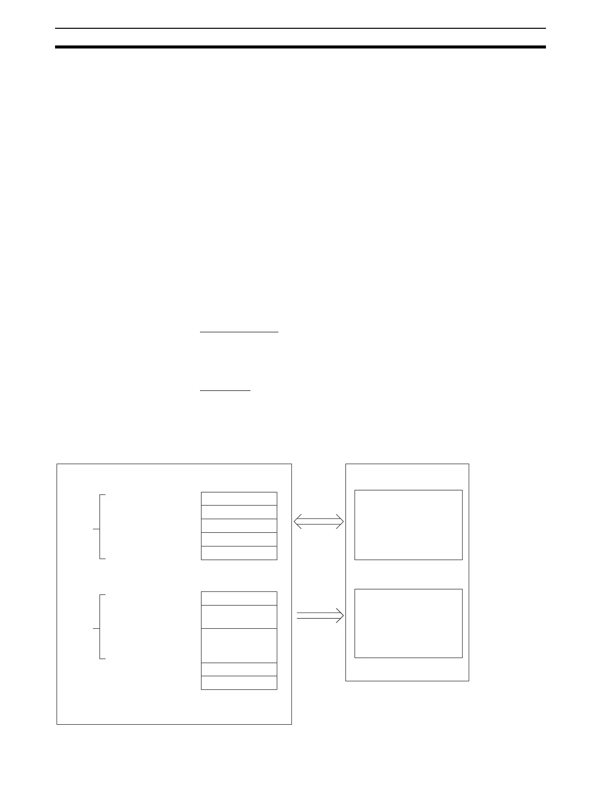
4-5 Exchanging Data with the CPU Unit
4-5-1 Outline of Data Exchange
Data is exchanged between the CPU Unit and the CS1W-DA08V/08C/041
Analog Output Unit via the Special I/O Unit Area (for data used to operate the
Unit) and the Special I/O Unit DM Area (for data used for initial settings).
I/O Refresh Data
Analog output setting values and other data used to operate the Unit are allo-
cated in the Special I/O Unit Area of the CPU Unit according to the unit num-
ber, and are exchanged during I/O refreshing.
Fixed Data
The Unit’s fixed data, such as the analog output signal ranges and the output
status when conversion is stopped, is allocated in the Special I/O Unit DM
Area of the CPU Unit according to the unit number, and is exchanged when
the power is turned ON or the Unit is restarted.
CS-series CPU Unit
CS1W-DA08V/08C/041 Analog Output Unit
Special I/O Unit Area I/O Refresh Data
Analog outputs
DM (Data Memory) Area
Analog output
ranges
Output status
when conversion
stopped
I/O refresh
Power ON or
Unit restart
Exchanges analog output
values exchanged during
data refresh.
Transmits fixed data such
as conversion stop v
alues
and analog output ranges.
2000 + n x 10
2000 + n x 10 + 9
D20000 + n x 100
D20000 + n x 100 + 99
10
words
100
w
ords
Fixed Data
:
:
n: Unit number
See Allocations for
Normal Mode on
page 147 for
details.
See DM Allocation
Contents on
page 145 for
details.
 Loading...


