31
Components and Switch Settings Section 2-3
Relationship between Operation Mode Switch Setting and DM Area
Setting
The Unit will operate in normal mode when both the operation mode switch
and DM Area setting are set to normal mode. If either or both of the settings
are set to adjustment mode, the Unit will operate in adjustment mode. The
operation mode will change whenever the power is restarted or any of the
Special I/O Unit Restart Bits (A502 to A507) turn ON.
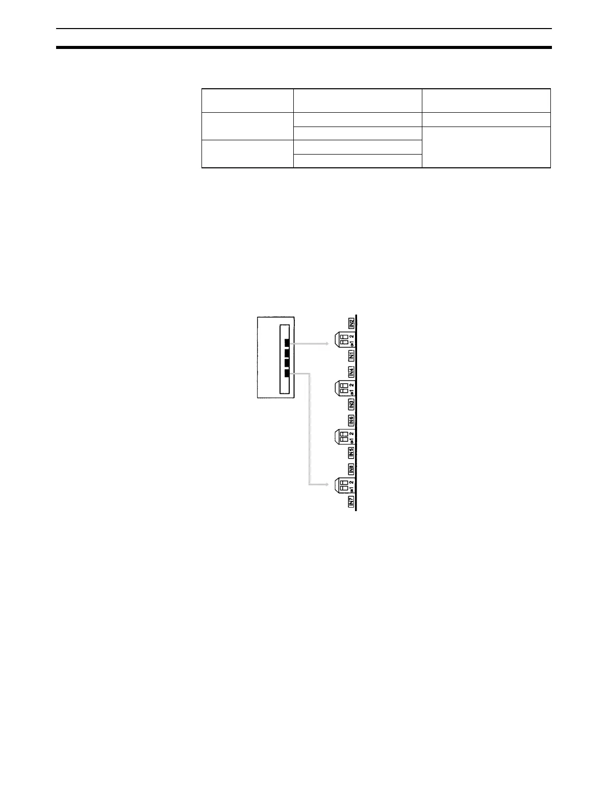
2-3-4 Voltage/Current Switch (CS1W-AD041-V1/AD081-V1)
The analog conversion input can be switched from voltage input to current
input by changing the pin settings on the voltage/current switch located on the
back of the terminal block.
Note 1. There are only four inputs for the CS1W-AD041-V1.
2. With CS1W-AD161, select voltage/current input by wiring the connector
terminals.
!Caution Be sure to turn OFF the power to the PLC before mounting or removing the
terminal block or connector.
Operation mode
switch
DM Area setting Analog Input Unit operation
mode
Normal mode
(default)
Normal mode Normal mode
Adjustment mode Adjustment mode
Adjustment mode Normal mode
Adjustment mode
IN1: Input 1
IN4: Input 4
OFF: Voltage inpu
ON: Current input
IN3: Input 3
IN6: Input 6
IN2: Input 2
IN5: Input 5
IN8: Input 8
IN7: Input 7
 Loading...


