200
Analog Output Functions and Operating Procedures Section 5-6
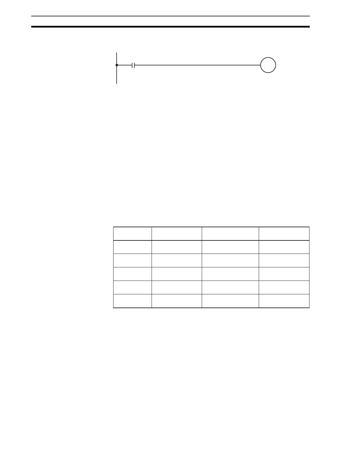
In this example, conversion is begun for analog output number 1. (The unit
number is 0.)
5-6-4 Output Hold Function
The Analog Output Unit stops conversion under the following circumstances
and outputs the value set by the output hold function.
1,2,3... 1. When the Conversion Enable Bit is OFF. Refer to Allocations for Normal
Mode on page 193 and 5-6-3 Starting and Stopping Conversion.
2. In adjustment mode, when something other than the output number is out-
put during adjustment. Refer to Allocation for Adjustment Mode on
page 195.
3. When there is an output setting error. Refer to Allocations for Normal Mode
on page 193 and page 204.
4. When a fatal error occurs at the PLC.
5. When there is an I/O bus error.
6. When the CPU Unit is in LOAD OFF status.
7. When there is a WDT (watchdog timer) error in the CPU Unit.
CLR, HOLD, or MAX can be selected for the output status when conversion is
stopped.
The above values may fluctuate if offset/gain adjustment has been applied.
200000
Input condition
Conversion
begins for
output
number 1.
Output signal
range
CLR HOLD MAX
0 to 10 V –0.5 V (Min. –5% of
full scale)
Voltage that was output
just prior to stop.
10.5 V (Max. +5% of
full scale)
–10 to 10 V 0.0 V Voltage that was output
just prior to stop.
11.0 V (Max. +5% of
full scale)
1 to 5 V 0.8 V (Min. –5% of
full scale)
Voltage that was output
just prior to stop.
5.2 V (Max. +5% of
full scale)
0 to 5 V –0.25 V (Min. –5%
of full scale)
Voltage that was output
just prior to stop.
5.25 V (Max. +5% of
full scale)
4 to 20 mA 3.2 mA (Min. –5% of
full scale)
Current that was output
just prior to stop.
20.8 mA (Max. +5%
of full scale)
 Loading...


