318
Analog Input Functions and Operating Procedures Section 7-6
The input disconnection detection function can be used when the input signal
range is set for 1 to 5 V (4 to 20 mA).
7-6 Analog Input Functions and Operating Procedures
7-6-1 Input Settings and Conversion Values
Setting Inputs and Signal Ranges
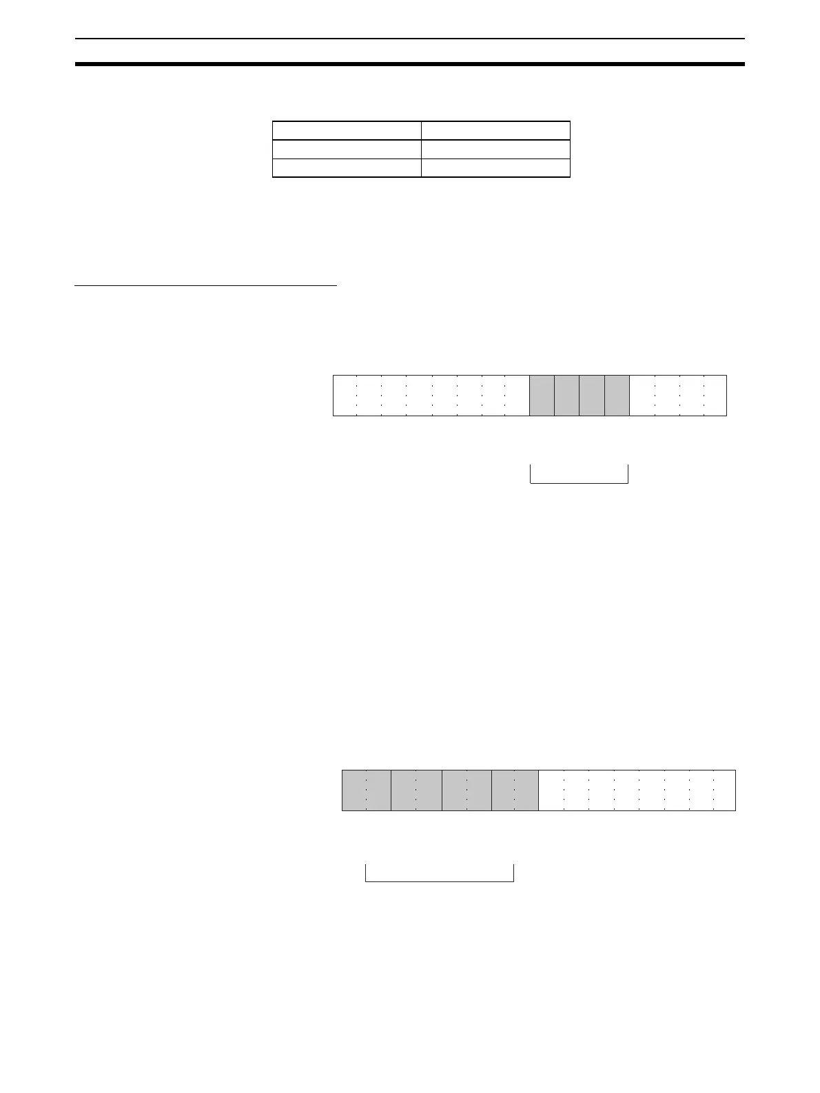
Input Numbers The Analog I/O Unit converts only analog inputs specified by input numbers 1
to 4. To specify the analog inputs to be used, turn ON from a Programming
Device the D(m) bits in the DM Area shown in the following diagram.
The analog input sampling interval can be shortened by setting any unused
input numbers to 0.
Sampling interval = (1 ms) (See note.) x (Number of inputs used)
For the DM word addresses, m = D20000 + (unit number x 100)
The word for inputs that have been set to “Not used” will always be “0000.”
Note This value will be 500
µs when the setting is for 500 µs and a resolution of
8,000.
Input Signal Range Any of four types of input signal range (–10 to 10 V, 0 to 10 V, 1 to 5 V, and 4
to 20 mA) can be selected for each of the inputs (i.e., input numbers 1 to 4).
To specify the input signal range for each input, set from a Programming
Device the D(m+1) bits in the DM Area as shown in the following diagram.
Note 1. For the DM word addresses, m = D20000 + (unit number x 100)
2. The input signal range of “1 to 5 V” or “4 to 20 mA” is switched using the
voltage/current switch.
Input signal range Voltage/current
1 to 5 V 0.3 V max.
4 to 20 mA 1.2 mA max.
15 14 13 12 11 10 09 08 07 06 05 04 03 02 01 00
Bit
D(m)
Input 2
Input 1
0: Not used
1: Used
Input 4
Input 3
15 14 13 12 11 10 09 08 07 06 05 04 03 02 01 00
Bit
D(m+1)
Input 2
Input 1
00: −10 to 10 V
01: 0 to 10 V
10: 1 to 5 V / 4 to 20 mA
11: 0 to 5 V
Input 4
Input 3
 Loading...


