EasyManua.ls Logo

Omron CS1W-AD081-V1 User Manual

Omron CS1W-AD081-V1
427 pages
To Next Page IconTo Next Page
To Previous Page IconTo Previous Page
Page #342 background imageLoading...
Page #342 background image
319
Analog Input Functions and Operating Procedures Section 7-6
3. After making the DM settings from a Programming Device, it will be neces-
sary to either turn the power to the PLC OFF and ON, or turn ON the Spe-
cial I/O Unit Restart Bit in order to transfer the contents of the DM settings
to the Special I/O Unit.
Voltage/Current Range
Setting
When “1 to 5 V, 4 to 20 mA” is selected for the input signal range, either the “1
to 5 V” or “4 to 20 mA” range can then be selected by means of the D(m+35)
setting. Adjusting the factory-set voltage and current can improve the accu-
racy of current output specifications.
Reading Conversion
Values
Analog input conversion values are stored for each input number, in CIO
words n+5 to n+8.
Note For the CIO word addresses, n = CIO 2000 + (unit number x 10).
Use MOV(021) or XFER(070) to read conversion values in the user program.
Example 1 In this example, the conversion data from only one input is read. (The unit
number is 0.)
Example 2 In this example, the conversion data from multiple inputs is read. (The unit
number is 0.)
For details regarding conversion value scaling, refer to Scaling on page 366.
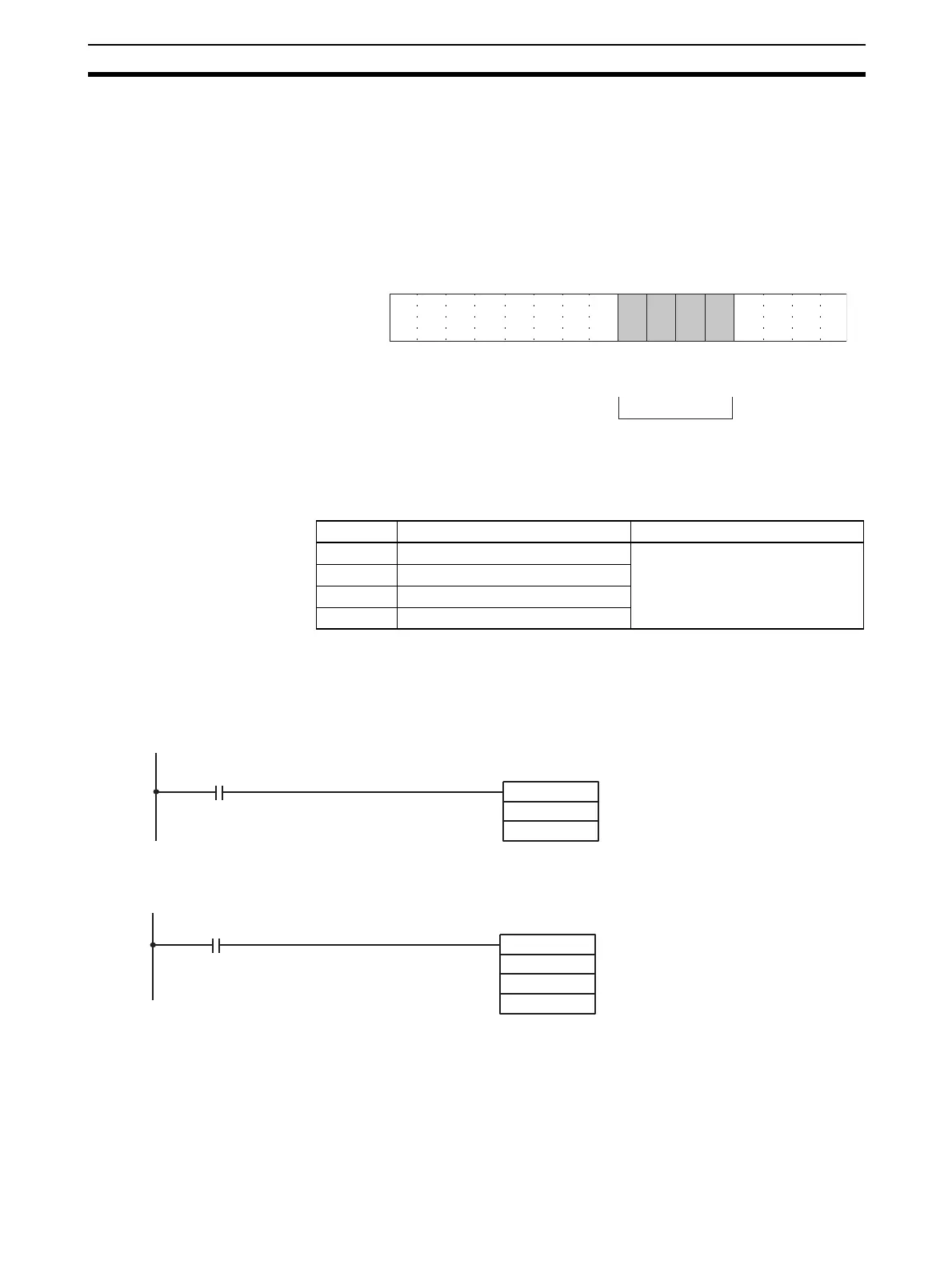
15 14 13 12 11 10 09 08 07 06 05 04 03 02 01 00
Bit
D(m+35)
Input 2
Input 1
0: Voltage: 1 V to 5 V
1: Current 4 mA to 20 mA
Input 4
Input 3
Word Function Stored value
n+5 Input 1 conversion value 16-bit binary data
n+6 Input 2 conversion value
n+7 Input 3 conversion value
n+8 Input 4 conversion value
MOV(021)
2005
D00001
Input condition
Conversion data in CIO word
2005 (input number 1) is read
to D00001.
XFER(070)
#0004
2005
D00001
Input condition
Conversion data in CIO words
2005 and 2008 (input num-
bers 1 and 4) is read to
D00001 and D00004.

Table of Contents

Questions and Answers:

Omron CS1W-AD081-V1 Specifications

General IconGeneral
Number of Channels8
Power Supply5 V DC
Operating Temperature0 to 55 °C
TypeAnalog Input
Input Range0 to 10 V, 0 to 20 mA, 4 to 20 mA
Sampling Time/Conversion Time1ms per channel
Current Consumption100 mA
IsolationPhotocoupler isolation between input and internal circuit
Storage Temperature-25 to 65 °C
Relative Humidity35 to 85% (with no condensation)
Noise Immunity±2 kV
StandardsCE, UL

Summary

SYSMAC CS/CJ Series

Analog I/O Units

Describes the types of analog I/O units covered in the manual, including input, output, and combined units.

PRECAUTIONS

General Precautions

Fundamental safety and operational guidelines for using OMRON products.

Safety Precautions

Critical safety warnings and procedures to prevent injury or damage.

Application Considerations

SECTION 2 CS-series Analog Input Units

2-2 Operating Procedure

Step-by-step instructions for operating CS-series Analog Input Units.

2-6 Analog Input Functions and Operating Procedures

Details on analog input functions and their operational procedures.

2-8 Handling Errors and Alarms

Troubleshooting guide for errors and alarms in Analog Input Units.

SECTION 3 CJ-series Analog Input Units

3-2 Operating Procedure

Step-by-step instructions for operating CJ-series Analog Input Units.

3-6 Analog Input Functions and Operating Procedures

Details on analog input functions and their operational procedures.

3-8 Handling Errors and Alarms

Troubleshooting guide for errors and alarms in Analog Input Units.

SECTION 4 CS-series Analog Output Units

4-2 Operating Procedure

Step-by-step instructions for operating CS-series Analog Output Units.

4-6 Analog Output Functions and Operating Procedures

Details on analog output functions and their operational procedures.

4-8 Handling Errors and Alarms

Troubleshooting guide for errors and alarms in Analog Output Units.

SECTION 5 CJ-series Analog Output Unit

5-2 Operating Procedure

Step-by-step instructions for operating CJ-series Analog Output Units.

5-6 Analog Output Functions and Operating Procedures

Details on analog output functions and their operational procedures.

5-8 Handling Errors and Alarms

Troubleshooting guide for errors and alarms in Analog Output Units.

SECTION 6 CS-series Analog I/O Unit

6-2 Operating Procedure

Step-by-step instructions for operating CS-series Analog I/O Units.

6-6 Analog Input Functions and Operating Procedures

Details on analog input functions and their operational procedures.

6-7 Analog Output Functions and Operating Procedures

Details on analog output functions and their operational procedures.

6-10 Handling Errors and Alarms

Troubleshooting guide for errors and alarms in Analog I/O Units.

SECTION 7 CJ-series Analog I/O Unit

7-2 Operating Procedure

Step-by-step instructions for operating CJ-series Analog I/O Units.

7-6 Analog Input Functions and Operating Procedures

Details on analog input functions and their operational procedures.

7-7 Analog Output Functions and Operating Procedures

Details on analog output functions and their operational procedures.

7-10 Handling Errors and Alarms

Troubleshooting guide for errors and alarms in Analog I/O Units.

Appendix B Sample Programs

Appendix C Data Memory Coding Sheets

Related product manuals