60
Adjusting Offset and Gain Section 2-7
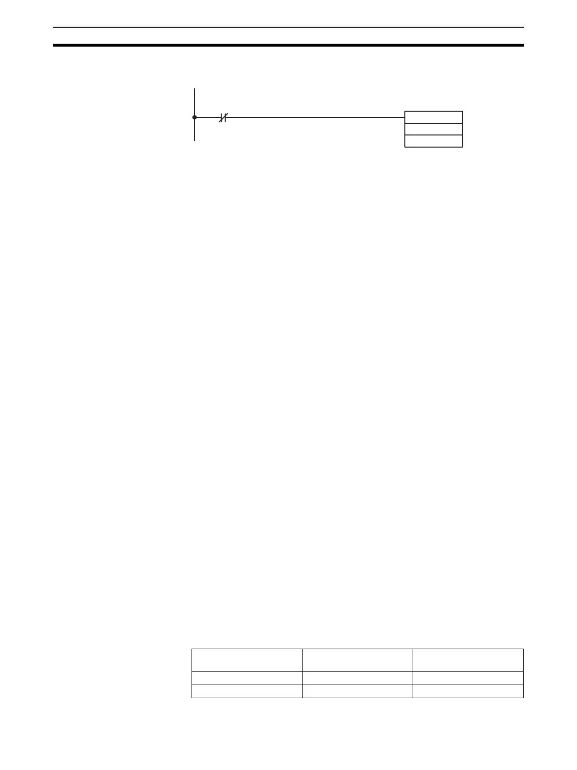
In the following example, the conversion value is read only if there is no dis-
connection at analog input number 1. (The unit number is 0.)
2-6-6 Scaling Function (CS1W-AD161 Only)
With the CS1W-AD161, the scaling function can be used to convert data into
engineering units after A/D conversion. The scaling function can only be used
when the resolution is set to 4,000. Scaling is not supported for resolutions of
8,000.
Overview When using a resolution of 4,000, A/D conversion data in the ranges 1 to 5 V,
0 to 5 V, 0 to 10 V, or 4 to 20 mA will be scaled to values between 0 and 4,000
(BCD), approximately. A/D conversion data in the range
−10 to +10 V will be
scaled to values between
−2,000 and +2,000 (BCD), approximately. (Actual D/
A conversion is executed up to
−5% to +105% of full scale.)
The lower limit and upper limit can be set to between −32000 and +32000
(BCD). Actual settings in DM word m+20 to DM word m+51 are set in 4-digit
hexadecimal. (In the above example, the lower limit is 0000 and the upper
limit is 2710 hexadecimal.)
• Besides upper limit and lower limit. (Reverse scaling is supported.)
• Negative values are set as two's complement
• Scaling is not performed when the upper limit and lower limit are both set
to 0000 (default setting).
2-7 Adjusting Offset and Gain
2-7-1 Adjustment Mode Operational Flow
The adjustment mode enables the input of the connected devices to be cali-
brated.
The offset voltage (or current) and gain voltage (or current) at the output
device are entered as analog input conversion data 0000 and 0FA0 (07D0 if
the range is
±10 V) respectively for a resolution of 4,000.
For example, when using in the range 1 to 5 V, the actual output may be in the
range 0.8 to 4.8 V, even though the specifications range for the external
device is 1 to 5 V. In this case, when an offset voltage of 0.8 V is output at the
external device, the conversion data at the Analog Input Unit for a resolution
of 4,000 will be FF38, and if a gain voltage of 4.8 V is output, the conversion
data will be 0EDA. The offset/gain adjustment function will, for this example,
convert 0.8 V and 4.8 V to 0000 and 0FA0 respectively and not to FF38 and
0EDA, as illustrated in the following table.
(Values in parentheses are for a resolution of 8,000.)
MOV (021)
2001
D00001
200901
The conver-
sion value in
CIO word
2001 (input
number 1) is
read to
D00001.
Offset/gain voltage at the
output device
Conversion data before
adjustment
Conversion data after
adjustment
0.8 V FF38 (FE70) 0000 (0000)
4.8 V 0EDA (0DB4) 0FA0 (1F40)
 Loading...


