124
Handling Errors and Alarms Section 3-8
3-8-4 Restarting Special I/O Units
There are two ways to restart Special I/O Unit operation after having changed
DM contents or having cleared the cause of an error. The first way is to turn
the power to the PLC OFF and ON, and the second way is to turn ON the
Special I/O Unit Restart Bit ON.
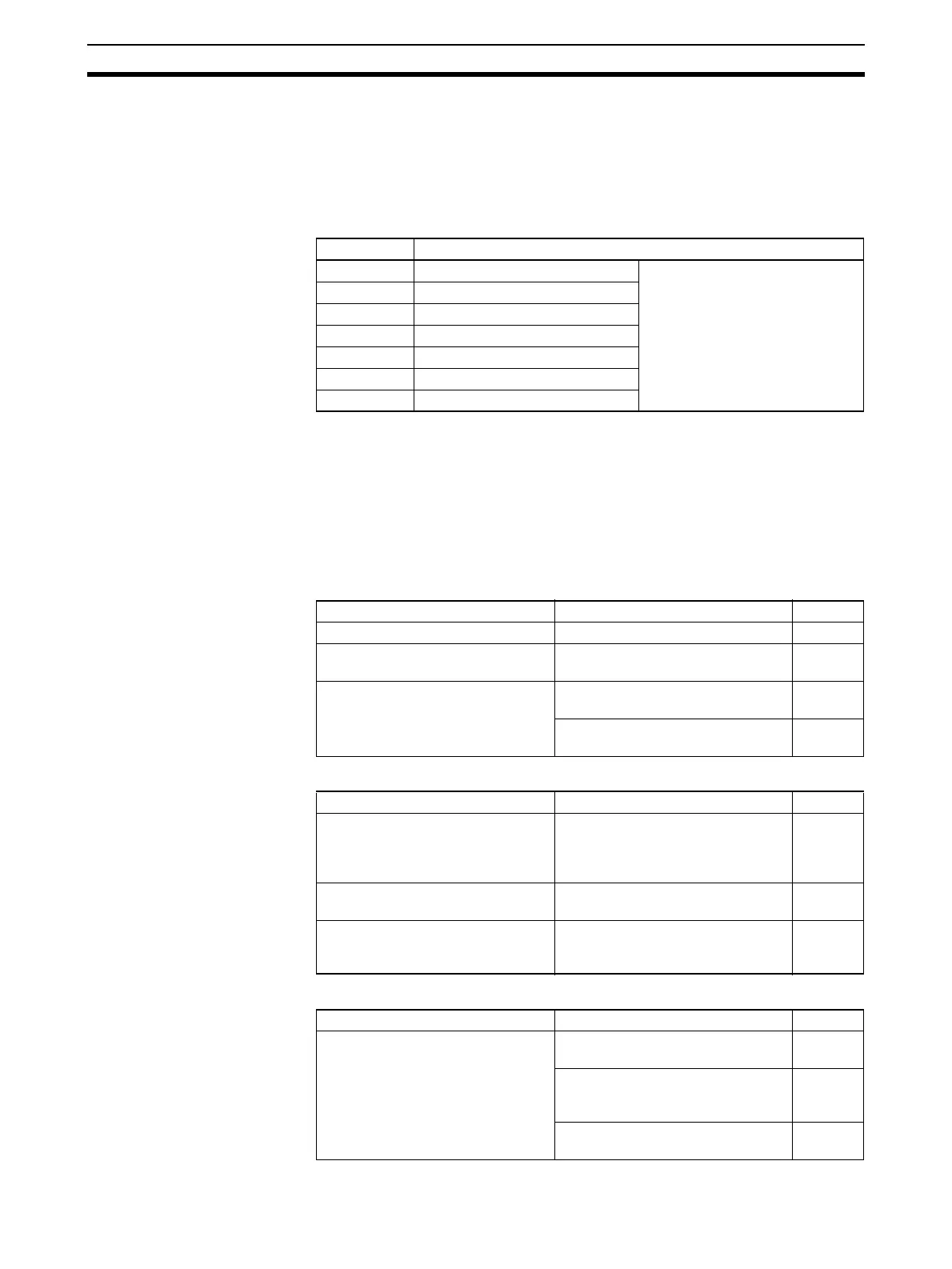
Special I/O Unit Restart Bits
The conversion data becomes 0000 during restart.
If the error is not cleared even after turning the Special I/O Unit Restart Bit ON
and then OFF again, then replace the Unit.
3-8-5 Troubleshooting
The following tables explain the probable causes of troubles that may occur,
and the countermeasures for dealing with them.
Conversion Data Does Not Change
Value Does Not Change as Intended
Conversion Values are Inconsistent
Bits Functions
A50200 Unit #0 Restart Bit Turning the Restart Bit for any
Unit ON and then OFF again
restarts that Unit.
A50201 Unit #1 Restart Bit
~~
A50215 Unit #15 Restart Bit
A50300 Unit #16 Restart Bit
~~
A50715 Unit #95 Restart Bit
Probable cause Countermeasure Page
The input is not set for being used. Set the input to be used. 104
The peak value hold function is in
operation.
Turn OFF the peak value hold func-
tion if it is not required.
110
The input device is not working, the
input wiring is wrong, or there is a
disconnection.
Using a tester, check to see if the
input voltage or current is changing.
---
Use Unit’s alarm flags to check for a
disconnection.
121
Probable cause Countermeasure Page
The input device’s signal range
does not match the input signal
range for the relevant input number
at the Analog Input Unit.
Check the specifications of the
input device, and match the settings
for the input signal ranges.
78
The offset and gain are not
adjusted.
Adjust the offset and gain. 112
When using the 4 mA to 20 mA
range, the voltage/current switch is
not turned ON.
Turn ON the voltage/current switch. 92
Probable cause Countermeasure Page
The input signals are being affected
by external noise.
Change the shielded cable connec-
tion to the Unit’s COM terminal.
96
Insert a 0.01-µF to 0.1-µF ceramic
capacitor or film capacitor between
the input’s (+) and (–) terminals.
---
Try increasing the number of mean
value processing buffers.
107
 Loading...


