252
Analog Input Functions and Operating Procedures Section 6-6
Note For the CIO word addresses, n = CIO 2000 + (unit number x 10).
The input disconnection detection function can be used when the input signal
range is set for 1 to 5 V (4 to 20 mA).
6-6 Analog Input Functions and Operating Procedures
6-6-1 Input Settings and Conversion Values
Setting Inputs and Signal Ranges
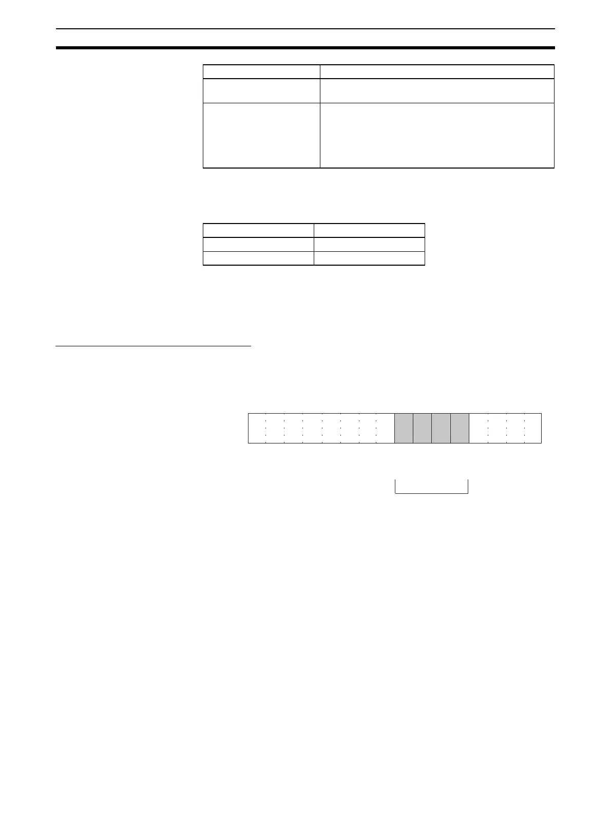
Input Numbers The Analog I/O Unit converts only analog inputs specified by input numbers 1
to 4. To specify the analog inputs to be used, turn ON from a Programming
Device the D(m) bits in the DM Area shown in the following diagram.
The analog input sampling interval can be shortened by setting any unused
input numbers to 0.
Sampling interval = (1 ms) x (Number of inputs used)
For the DM word addresses, m = D20000 + (unit number x 100)
The word for inputs that have been set to “Not used” will always be “0000.”
Disconnection detection 0: No disconnection
1: Disconnection
Alarm Flags Bit 12: Input value is outside adjustment limits
(in adjustment mode)
Bit 13: I/O number setting error (in adjustment mode)
Bit 14: EEPROM write error (in adjustment mode)
Bit 15: Operating in adjustment mode
(always 1 in adjustment mode)
Item Contents
Input signal range Voltage/current
1 to 5 V 0.3 V max.
4 to 20 mA 1.2 mA max.
15 14 13 12 11 10 09 08 07 06 05 04 03 02 01 00
Bit
D(m)
Input 2
Input 1
0: Not used
1: Used
Input 4
Input 3
 Loading...


