121
Handling Errors and Alarms Section 3-8
3-8-2 Alarms Occurring at the Analog Input Unit
When an alarm occurs at the Analog Input Unit, the ERC indicator lights and
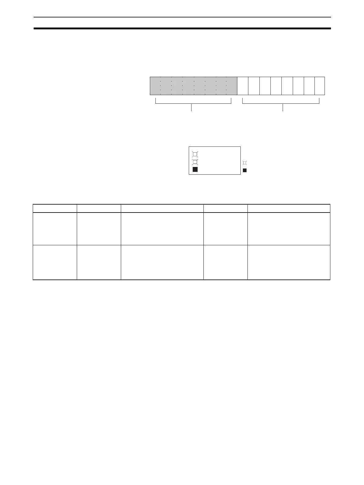
the Alarm Flags are stored in bits 08 to 15 of CIO word n+9.
ERC and RUN Indicators: Lit
The ERC and RUN indicators will be lit when an error occurs while the Unit is
operating normally. The following alarm flags will turn ON in CIO word n+9.
These alarm flags will turn OFF automatically when the error is cleared.
Note 1. With the CJ1W-AD041-V1, the Disconnection Detection Flags are stored
in bits 00 to 03. Bits 04 to 07 are not used (always OFF).
2. Disconnection detection operates for input numbers used with a range of
1 to 5 V (4 to 20 mA).
15 14 13 12 11 10 09 08 07 06 05 04 03 02 01 00
Bit
Word n+9
Disconnection Detection Flags
Alarm Flags
(With the CJ1W -AD041-V1, bits 00 to 03
RUN
ERC
ERH
: Lit
: Not lit
Word n + 9 Alarm flag Error contents Input status Countermeasure
Bits 00 to 07
(See note 1.)
Disconnection
Detection
A disconnection was detected.
(See note 2.)
Conversion data
becomes 0000.
Check the rightmost byte of CIO
word n+9. The inputs for bits
that are ON may be discon-
nected. Restore any discon-
nected inputs.
Bit 14 (Adjustment
mode)
EEPROM Writ-
ing Error
An EEPROM writing error has
occurred while in adjustment
mode.
Holds the values
immediately
prior to the error.
No data is
changed.
Turn the Set Bit OFF, ON, and
OFF again.
If the error persists even after
the reset, replace the Analog
Input Unit.
 Loading...


