EasyManua.ls Logo

Omron CS1W-AD081-V1 User Manual

Omron CS1W-AD081-V1
427 pages
To Next Page IconTo Next Page
To Previous Page IconTo Previous Page
Page #173 background imageLoading...
Page #173 background image
150
Analog Output Functions and Operating Procedures Section 4-6
Output Signal Range Any of four types of output signal range (–10 to 10 V, 0 to 10 V, 1 to 5 V/4 to
20 mA, and 0 to 5 V) can be selected for each of the outputs. To specify the
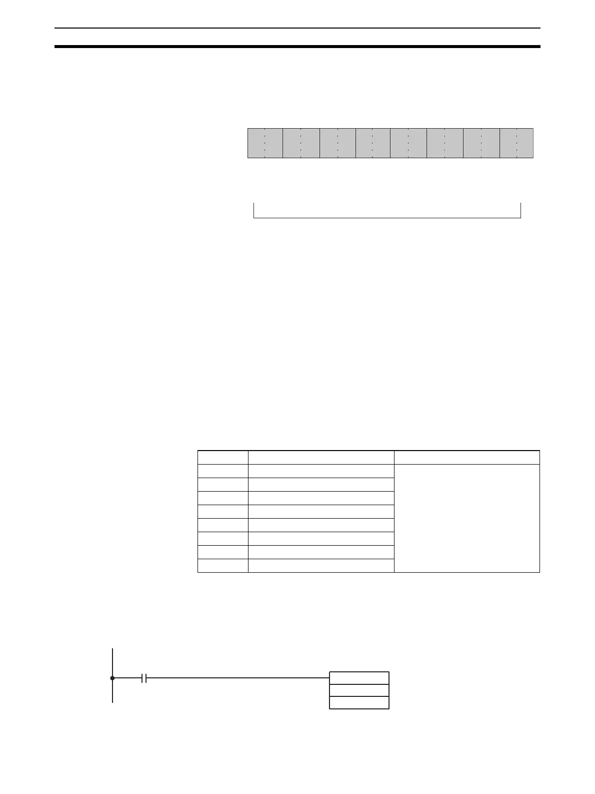
output signal range for each output, use a Programming Device to set the
D(m+1) bits in the DM Area shown in the following diagram.
Note 1. For the DM word addresses, m = D20000 + (unit number x 100).
2. With the CS1W-DA041, the 1 to 5 V output range and the 4 to 20 mA output
range are switched by changing the terminal connections.
3. There is no 4 to 20 mA output range for the CS1W-DA08V.
4. Output setting range settings for the CS1W-DA08C are invalid. The output
signal range will be 4 to 20 mA, regardless of the settings.
5. When data memory settings have been carried out using a Programming
Device, be sure to either turn the power supply for the PLC OFF and then
ON again, or set the Special I/O Unit Restart Bit to ON. The contents of the
data memory settings will be transferred to the Special I/O Unit when the
power is turned ON or the Special I/O Unit Restart Bit is ON.
Writing Set Values Analog output set values are written to CIO words (n+1) to (n+8). For the
CS1W-DA041, they are written to CIO words (n+1) to (n+4).
For the CIO word addresses, n = CIO 2000 + (unit number x 10).
Use MOV(021) or XFER(070) to write values in the user program.
Example 1 In this example, the set value from only one output is written. (The unit num-
ber is 0.)
15 14 13 12 11 10 09 08 07 06 05 04 03 02 01 00
Bit
D(m + 1)
Output 2
Output 1
00: 10 to 10 V
01: 0 to 10 V
10: 1 to 5 V/4 to 20 mA
11: 0 to 5 V
Output 4
Output 3
Output 6
Output 5
Output 8
Output 7
Word Function Stored value
n+1 Output 1 set value 16-bit binary data
n+2 Output 2 set value
n+3 Output 3 set value
n+4 Output 4 set value
n+5 Output 5 set value
n+6 Output 6 set value
n+7 Output 7 set value
n+8 Output 8 set value
MOV (021)
D00001
2001
Input condition
The set value stored in D 00001
is written to CIO word 2001 (out-
put number 1).

Table of Contents

Questions and Answers:

Omron CS1W-AD081-V1 Specifications

General IconGeneral
Number of Channels8
Power Supply5 V DC
Operating Temperature0 to 55 °C
TypeAnalog Input
Input Range0 to 10 V, 0 to 20 mA, 4 to 20 mA
Sampling Time/Conversion Time1ms per channel
Current Consumption100 mA
IsolationPhotocoupler isolation between input and internal circuit
Storage Temperature-25 to 65 °C
Relative Humidity35 to 85% (with no condensation)
Noise Immunity±2 kV
StandardsCE, UL

Summary

SYSMAC CS/CJ Series

Analog I/O Units

Describes the types of analog I/O units covered in the manual, including input, output, and combined units.

PRECAUTIONS

General Precautions

Fundamental safety and operational guidelines for using OMRON products.

Safety Precautions

Critical safety warnings and procedures to prevent injury or damage.

Application Considerations

SECTION 2 CS-series Analog Input Units

2-2 Operating Procedure

Step-by-step instructions for operating CS-series Analog Input Units.

2-6 Analog Input Functions and Operating Procedures

Details on analog input functions and their operational procedures.

2-8 Handling Errors and Alarms

Troubleshooting guide for errors and alarms in Analog Input Units.

SECTION 3 CJ-series Analog Input Units

3-2 Operating Procedure

Step-by-step instructions for operating CJ-series Analog Input Units.

3-6 Analog Input Functions and Operating Procedures

Details on analog input functions and their operational procedures.

3-8 Handling Errors and Alarms

Troubleshooting guide for errors and alarms in Analog Input Units.

SECTION 4 CS-series Analog Output Units

4-2 Operating Procedure

Step-by-step instructions for operating CS-series Analog Output Units.

4-6 Analog Output Functions and Operating Procedures

Details on analog output functions and their operational procedures.

4-8 Handling Errors and Alarms

Troubleshooting guide for errors and alarms in Analog Output Units.

SECTION 5 CJ-series Analog Output Unit

5-2 Operating Procedure

Step-by-step instructions for operating CJ-series Analog Output Units.

5-6 Analog Output Functions and Operating Procedures

Details on analog output functions and their operational procedures.

5-8 Handling Errors and Alarms

Troubleshooting guide for errors and alarms in Analog Output Units.

SECTION 6 CS-series Analog I/O Unit

6-2 Operating Procedure

Step-by-step instructions for operating CS-series Analog I/O Units.

6-6 Analog Input Functions and Operating Procedures

Details on analog input functions and their operational procedures.

6-7 Analog Output Functions and Operating Procedures

Details on analog output functions and their operational procedures.

6-10 Handling Errors and Alarms

Troubleshooting guide for errors and alarms in Analog I/O Units.

SECTION 7 CJ-series Analog I/O Unit

7-2 Operating Procedure

Step-by-step instructions for operating CJ-series Analog I/O Units.

7-6 Analog Input Functions and Operating Procedures

Details on analog input functions and their operational procedures.

7-7 Analog Output Functions and Operating Procedures

Details on analog output functions and their operational procedures.

7-10 Handling Errors and Alarms

Troubleshooting guide for errors and alarms in Analog I/O Units.

Appendix B Sample Programs

Appendix C Data Memory Coding Sheets

Related product manuals