177
Operating Procedure Section 5-2
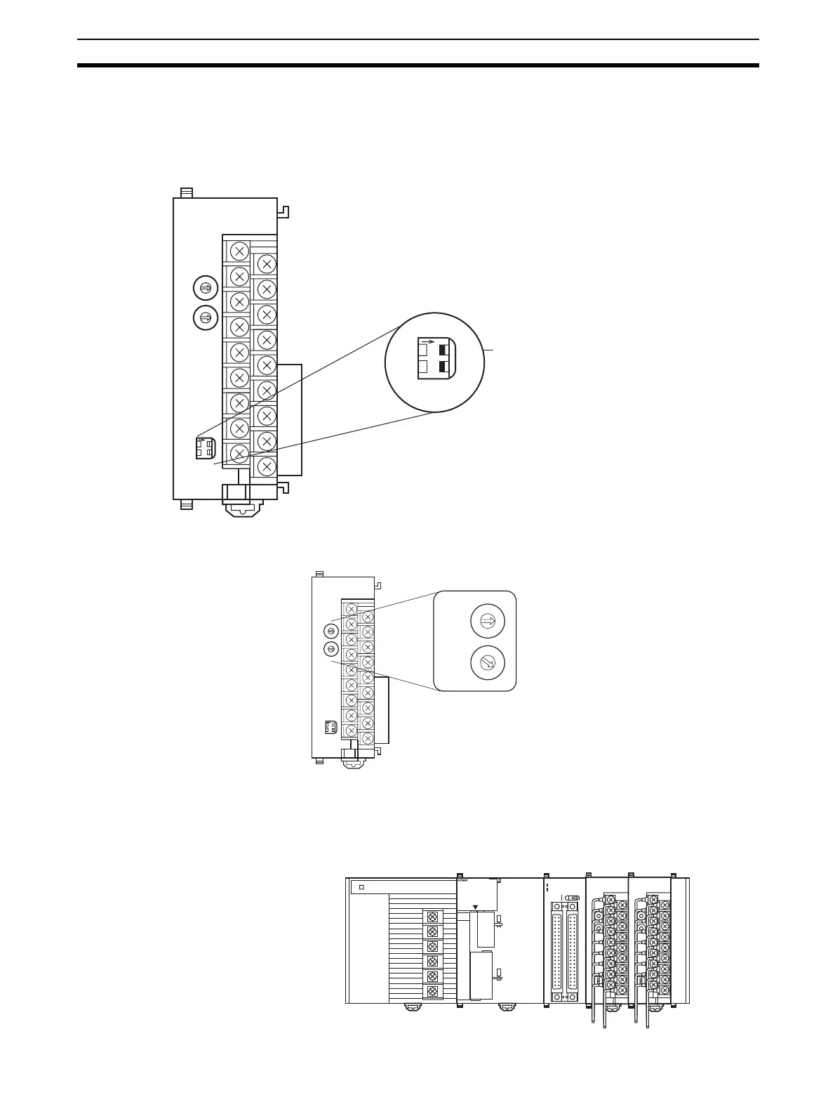
Setting the Analog Output Unit
1,2,3... 1. Set the operation mode switch on the front panel of the Unit. Refer to 5-3-
3 Operation Mode Switch (DA021/041) for further details.
The CJ1W-DA08V/08C does not have this switch. Change the mode by
making the setting in D(m+18).
2. Set the unit number switch. Refer to 5-3-2 Unit Number Switch for further
details.
3. Connect and wire the Analog Output Unit. Refer to 1-2-1 Mounting Proce-
dure, Note The CJ1W-DA08V/08C Analog Output Unit has a software set-
ting for the operation mode in bits 00 to 07 of DM word m+18. The contents
of DM word m+18 are shown below. or 5-4-3 Output Wiring Example for
further details.
MACH
No.
DA041
RUN
ERC
ERH
B1 A1
ADJ
x10
1
x10
0
0
9
8
7
6
5
4
3
2
1
0
9
8
7
6
5
4
3
2
1
O
N
12
MODE
OFF
OFF
O
N
12
MODE
Turn OFF SW1 for normal mode.
MACH
No.
DA041
RUN
ERC
ERH
B1 A1
ADJ
x10
1
x10
0
0
9
8
7
6
5
4
3
2
1
0
9
8
7
6
5
4
3
2
1
O
N
12
MODE
MACH
No.
10
1
10
0
0
9
8
7
6
5
4
3
2
1
0
9
8
7
6
5
4
3
2
1
If the unit number is set to 1, words will
be allocated to the Analog Input Unit in
Special I/O Unit Area CIO 2010 to
CIO 2019 and in the Special I/O Unit
Area D20100 to D20199.
OD261
SYSMAC
CJ1G-CPU44
PROGRAMMABLE
CONTROLLER
RUN
ERR/ALM
INH
PRPHL
COMM
OPEN
PERIHERAL
PORT
MCPWR
BUSY
01234567
8 9 10 11 12 13 14 15
20
1
CN1
DC24V 0.3A
1
20
CN2
B/A A
/B
0
1
2
3
01234567
8 9 10 11 12 13 14
15
AD081
B1 A1
MACH
No.
x10
1
x10
0
RUN
ERC
ERH
ADJ
MODE
12
DA041
B1 A1
MACH
No.
x10
1
x10
0
RUN
ERC
ERH
ADJ
MODE
12
 Loading...


